Community project
ve project, automatted rain water harvesting, plant monitoring hybrid
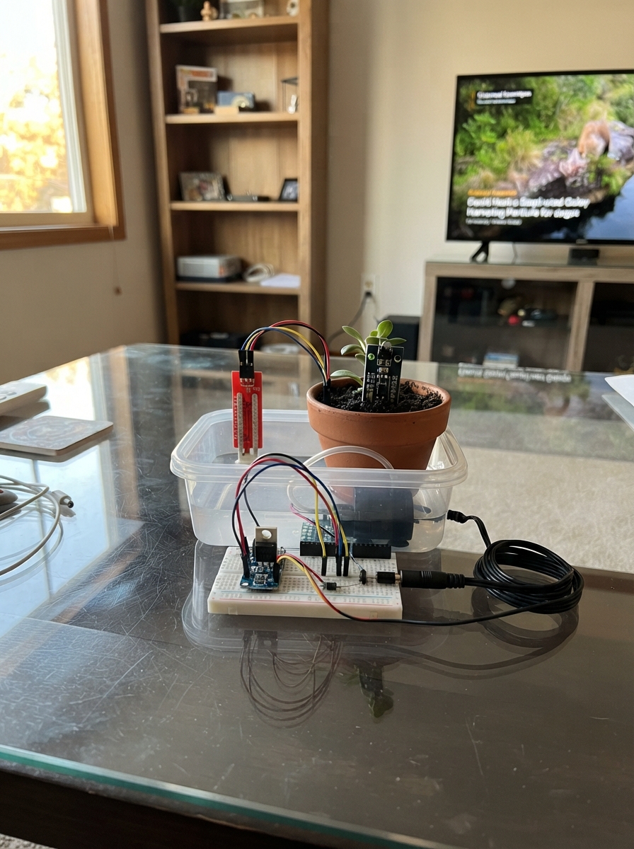
This automated rain water harvesting system combines tank level monitoring with soil moisture sensing to intelligently water plants while conserving resources. The ESP32 reads analog water levels from a harvesting tank and digital soil moisture signals, then activates a 12V submersible pump only when soil is dry and water is available—with safety cutoffs to prevent tank depletion.
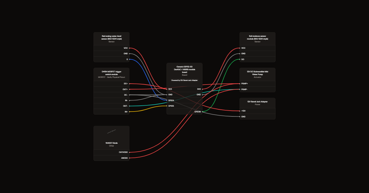
Builders will receive a complete wiring diagram showing sensor connections to the ESP32, the MOSFET pump trigger circuit with protection diode, a parts list with all components, step-by-step assembly instructions, and Arduino firmware with Telegram notifications. The guide includes calibration steps for setting water thresholds and soil dryness trip points specific to each installation.
Wiring diagram
Gather all the parts
Assemble it in 5 steps
1. Keep both power supplies unplugged
Leave the ESP32-S3 USB cable and the 12 V pump supply unplugged while fitting wires. Put the pump where it can move water without splashing the small board or breadboard.
- Keep every low-voltage board higher than the tank and away from splashes.
- Water on the ESP32-S3, switch board, or loose connections can cause a short circuit and damage the electronics.
2. Wire the two sensing boards
On the red water-level sensor, connect VCC → ESP32-S3 3V3 (power), GND → ESP32-S3 GND (ground), and S → GPIO4 (water-height signal). On the soil module, connect VCC → ESP32-S3 3V3 (power), GND → ESP32-S3 GND (ground), and DO → GPIO16 (dry-soil signal). These two signal pins are on the same header side used for the pump-control wire.
- Power both sensor boards from 3V3, not 5 V, so their output wires cannot overload the ESP32-S3 inputs.
- Place the red level strip at the height where you want the tank-full warning.
- Do not put 5 V on GPIO4 or GPIO16; the ESP32-S3 pins use 3.3 V and can be damaged by a higher signal.
3. Connect the ESP32-S3 to the pump switch
Connect the D4184 module IN+ → GPIO5 (pump command) and IN- → ESP32-S3 GND (signal ground). Also connect the D4184 DC- terminal → ESP32-S3 GND (shared ground). GPIO5 is on the same header side as the two sensor signal connections, so the three signal wires stay together.
- Read the labels printed beside the D4184 terminals carefully; IN+ and IN- are the small trigger input terminals, not the large pump terminals.
- The 12 V wire must never connect to GPIO5, 3V3, or any ESP32-S3 signal pin; doing that can destroy the board.
- If the D4184 input is not explicitly rated to recognize a 3.3 V signal, put a proper level converter between GPIO5 and IN+ instead of connecting it directly.
4. Wire the 12 V pump path and safety diode
Connect the 12 V supply positive wire → D4184 DC+ (pump power), and supply negative wire → D4184 DC- (power return). Connect D4184 OUT+ → pump PUMP+ (switched pump power) and D4184 OUT- → pump PUMP- (switched pump return). Put the 1N4007 diode directly across the pump: its striped Cathode end → pump PUMP+ (spike protection) and its unstriped Anode end → pump PUMP- (spike protection).
- Keep the diode leads short and insulate its bare legs so they cannot touch each other.
- Use a 12 V supply rated for at least the pump's running and start-up current; 2 A is a sensible minimum for a small pump.
- Reversing the diode makes it a short across the 12 V supply when the pump starts, which can overheat wires or damage the supply.
- Do not run the pump dry for long; it can overheat and fail.
5. Set the dry-soil trip point
Put the soil probes into soil at the dryness where watering should begin. Turn the small adjustment screw on the soil module slowly until its DO indicator changes state, then turn it a tiny amount farther toward the dry condition. The ESP32-S3 reads this DO signal every 100 milliseconds.
- The metal probes corrode faster if they are continuously powered in wet soil; inspect and clean them periodically.
- Keep the soil probe and its module connector dry above the soil line; moisture on the module can create wrong readings or a short circuit.
Review all connections
1. Connections between "water_level_sensor" and "ESP32"
2. Connections between "soil_moisture_sensor" and "ESP32"
3. Connections between "d4184_switch" and "ESP32"
4. Connections between "flyback_diode" and "ESP32"
5. Connections between "supply_12v" and "ESP32"
Deploy the firmware
#include <Arduino.h>
#include <WiFi.h>
#include <WiFiClientSecure.h>
#include <WiFiManager.h>
#include <UniversalTelegramBot.h>

constexpr uint8_t WATER_LEVEL_PIN = 4;
constexpr uint8_t SOIL_DO_PIN = 16;
constexpr uint8_t PUMP_TRIGGER_PIN = 5;

// Adjust these after observing the printed readings for your own tank.
constexpr int WATER_FULL_THRESHOLD = 1800;
constexpr int WATER_FULL_RESET_THRESHOLD = 1600;
// This module drives DO HIGH at its adjusted dry threshold; LOW means the soil is wet.
constexpr int SOIL_DRY_STATE = HIGH;
constexpr uint32_t SENSOR_INTERVAL_MS = 100;
constexpr uint32_t PUMP_RUN_MS = 5000;
constexpr uint32_t PUMP_RECHECK_PAUSE_MS = 1000;
constexpr uint32_t EMPTY_CONTAINER_TIMEOUT_MS = 5UL * 60UL * 1000UL;
constexpr uint32_t TELEGRAM_INTERVAL_MS = 1000;
constexpr uint32_t SERIAL_STATUS_INTERVAL_MS = 1000;
constexpr uint32_t WIFI_SEARCH_WINDOW_MS = 5000;

const char *BOT_TOKEN = "8514103811:AAHE93Tn1J2dfJWTQZMuvwLI9mpe_yhJDO8";
const char *AUTHORIZED_CHAT_ID = "8523967992";
// Home Wi-Fi used for Telegram. The controller keeps watering even if this network is unavailable.
const char *WIFI_SSID = "777";
const char *WIFI_PASSWORD = "12345678";

WiFiClientSecure telegramClient;
UniversalTelegramBot bot(BOT_TOKEN, telegramClient);
WiFiManager wifiManager;

bool tankWasFull = false;
bool automaticWateringEnabled = true;
bool manualPumpMode = false;
bool pumpRunning = false;
bool emptyContainerAlertSent = false;
bool wifiSearchFinished = false;
bool configPortalStarted = false;
uint32_t pumpStartedAt = 0;
uint32_t nextPumpAllowedAt = 0;
uint32_t dryWateringStartedAt = 0;
uint32_t lastSensorReadAt = 0;
uint32_t lastTelegramCheckAt = 0;
uint32_t lastSerialStatusAt = 0;
uint32_t wifiSearchStartedAt = 0;
int latestWaterReading = 0;
int latestSoilState = HIGH;

void setPump(bool on) {
  digitalWrite(PUMP_TRIGGER_PIN, on ? HIGH : LOW);
  pumpRunning = on;
  if (on) {
    pumpStartedAt = millis();
  }
  Serial.println(on ? "Pump: ON" : "Pump: OFF");
}

void sendMessage(const String &message) {
  if (WiFi.status() == WL_CONNECTED) {
    bot.sendMessage(AUTHORIZED_CHAT_ID, message, "");
  }
}

void handleTelegramMessages(int messageCount) {
  for (int i = 0; i < messageCount; i++) {
    const String chatId = bot.messages[i].chat_id;
    const String text = bot.messages[i].text;

    if (chatId != AUTHORIZED_CHAT_ID) {
      bot.sendMessage(chatId, "This controller is private.", "");
      continue;
    }

    if (text == "command1") {
      manualPumpMode = false;
      automaticWateringEnabled = true;
      emptyContainerAlertSent = false;
      nextPumpAllowedAt = millis();
      sendMessage("Automatic soil watering is enabled.");
    } else if (text == "command2") {
      manualPumpMode = false;
      automaticWateringEnabled = false;
      setPump(false);
      sendMessage("Pump stopped. Automatic soil watering is disabled.");
    } else if (text == "command3") {
      String status = "Water sensor: " + String(latestWaterReading);
      status += "\nTank: ";
      status += tankWasFull ? "full" : "not full";
      status += "\nSoil DO: ";
      status += latestSoilState == SOIL_DRY_STATE ? "dry threshold reached" : "not dry";
      status += "\nPump: ";
      status += pumpRunning ? "running" : "stopped";
      status += "\nAutomatic watering: ";
      status += automaticWateringEnabled ? "enabled" : "disabled";
      status += "\nManual pump mode: ";
      status += manualPumpMode ? "on" : "off";
      sendMessage(status);
    } else if (text == "command4") {
      automaticWateringEnabled = false;
      manualPumpMode = true;
      setPump(true);
      sendMessage("Pump switched on manually. Send command5 to switch it off.");
    } else if (text == "command5") {
      manualPumpMode = false;
      automaticWateringEnabled = false;
      setPump(false);
      sendMessage("Pump switched off manually. Automatic watering remains disabled.");
    } else if (text == "/start") {
      sendMessage("Commands:\ncommand1 - enable automatic watering\ncommand2 - stop the pump and disable automatic watering\ncommand3 - read tank, soil, and pump state\ncommand4 - switch the pump on manually\ncommand5 - switch the pump off manually");
    }
  }
}

void readAndControlSensors() {
  const uint32_t now = millis();
  if (now - lastSensorReadAt < SENSOR_INTERVAL_MS) {
    return;
  }
  lastSensorReadAt = now;

  latestWaterReading = analogRead(WATER_LEVEL_PIN);
  latestSoilState = digitalRead(SOIL_DO_PIN);

  if (!tankWasFull && latestWaterReading >= WATER_FULL_THRESHOLD) {
    tankWasFull = true;
    Serial.println("Tank: FULL");
    sendMessage("Water is full in rain water harvesting container.");
  } else if (tankWasFull && latestWaterReading <= WATER_FULL_RESET_THRESHOLD) {
    tankWasFull = false;
    Serial.println("Tank: no longer full");
  }

  const bool soilIsDry = latestSoilState == SOIL_DRY_STATE;
  if (!soilIsDry) {
    dryWateringStartedAt = 0;
    emptyContainerAlertSent = false;
  }

  if (pumpRunning && !manualPumpMode && now - pumpStartedAt >= PUMP_RUN_MS) {
    setPump(false);
    nextPumpAllowedAt = now + PUMP_RECHECK_PAUSE_MS;
  }

  if (automaticWateringEnabled && soilIsDry && dryWateringStartedAt != 0 &&
      now - dryWateringStartedAt >= EMPTY_CONTAINER_TIMEOUT_MS && !emptyContainerAlertSent) {
    emptyContainerAlertSent = true;
    automaticWateringEnabled = false;
    setPump(false);
    sendMessage("Rain water harvesting container empty; water plants manually or use water tank");
    Serial.println("Automatic watering stopped: container may be empty.");
  }

  if (automaticWateringEnabled && !pumpRunning && soilIsDry && !emptyContainerAlertSent && now >= nextPumpAllowedAt) {
    if (dryWateringStartedAt == 0) {
      dryWateringStartedAt = now;
    }
    setPump(true);
  }
}

void serviceWiFi() {
  const uint32_t now = millis();
  if (!wifiSearchFinished && now - wifiSearchStartedAt >= WIFI_SEARCH_WINDOW_MS) {
    wifiSearchFinished = true;
    const int foundNetworks = WiFi.scanComplete();
    if (foundNetworks >= 0) {
      Serial.printf("Wi-Fi scan finished: %d network(s) found.\n", foundNetworks);
      for (int i = 0; i < foundNetworks; ++i) {
        Serial.printf("  %s (%d dBm)\n", WiFi.SSID(i).c_str(), WiFi.RSSI(i));
      }
      WiFi.scanDelete();
    } else {
      Serial.println("Wi-Fi scan did not finish; continuing without Wi-Fi.");
    }

    if (WiFi.status() == WL_CONNECTED) {
      Serial.print("Wi-Fi connected: ");
      Serial.println(WiFi.localIP());
      sendMessage("Rain-harvesting controller is online. Send /start for commands.");
    } else {
      Serial.println("No saved Wi-Fi connected after 5 seconds. Sensors and automatic watering continue normally.");
      wifiManager.setConfigPortalBlocking(false);
      wifiManager.startConfigPortal("RainHarvest-Setup", "ChangeMe123");
      configPortalStarted = true;
      Serial.println("Wi-Fi setup network started: RainHarvest-Setup");
    }
  }

  if (configPortalStarted) {
    wifiManager.process();
    if (WiFi.status() == WL_CONNECTED) {
      configPortalStarted = false;
      Serial.print("Wi-Fi connected: ");
      Serial.println(WiFi.localIP());
      sendMessage("Rain-harvesting controller is online. Send /start for commands.");
    }
  }
}

void printSerialStatus() {
  const uint32_t now = millis();
  if (now - lastSerialStatusAt < SERIAL_STATUS_INTERVAL_MS) {
    return;
  }
  lastSerialStatusAt = now;
  Serial.printf("Water=%d | Soil=%s | Pump=%s | Auto=%s | Wi-Fi=%s\n",
                latestWaterReading,
                latestSoilState == SOIL_DRY_STATE ? "DRY" : "WET",
                pumpRunning ? "ON" : "OFF",
                automaticWateringEnabled ? "ON" : "OFF",
                WiFi.status() == WL_CONNECTED ? "connected" : "not connected");
}

void pollTelegram() {
  const uint32_t now = millis();
  if (WiFi.status() != WL_CONNECTED || now - lastTelegramCheckAt < TELEGRAM_INTERVAL_MS) {
    return;
  }
  lastTelegramCheckAt = now;

  int messageCount = bot.getUpdates(bot.last_message_received + 1);
  while (messageCount > 0) {
    handleTelegramMessages(messageCount);
    messageCount = bot.getUpdates(bot.last_message_received + 1);
  }
}

void setup() {
  Serial.begin(115200);
  delay(100);
  Serial.println("Rain-harvesting controller starting.");
  Serial.println("Searching for saved Wi-Fi for the first 5 seconds.");
  analogReadResolution(12);
  pinMode(SOIL_DO_PIN, INPUT);
  pinMode(PUMP_TRIGGER_PIN, OUTPUT);
  setPump(false);

  telegramClient.setInsecure();
  WiFi.mode(WIFI_STA);
  WiFi.begin(WIFI_SSID, WIFI_PASSWORD);
  WiFi.scanNetworks(true);
  wifiSearchStartedAt = millis();
}

void loop() {
  readAndControlSensors();
  serviceWiFi();
  pollTelegram();
  printSerialStatus();
  delay(1);
}
Remix this project
Make it yours in one click
Open a full copy of this project in your own Schematik workspace, diagram, code, parts, and assembly steps included. Swap the sensor, add features, or redesign the whole thing with AI. The author's original stays untouched.