Community project
Voice-Interactive Desk Buddy
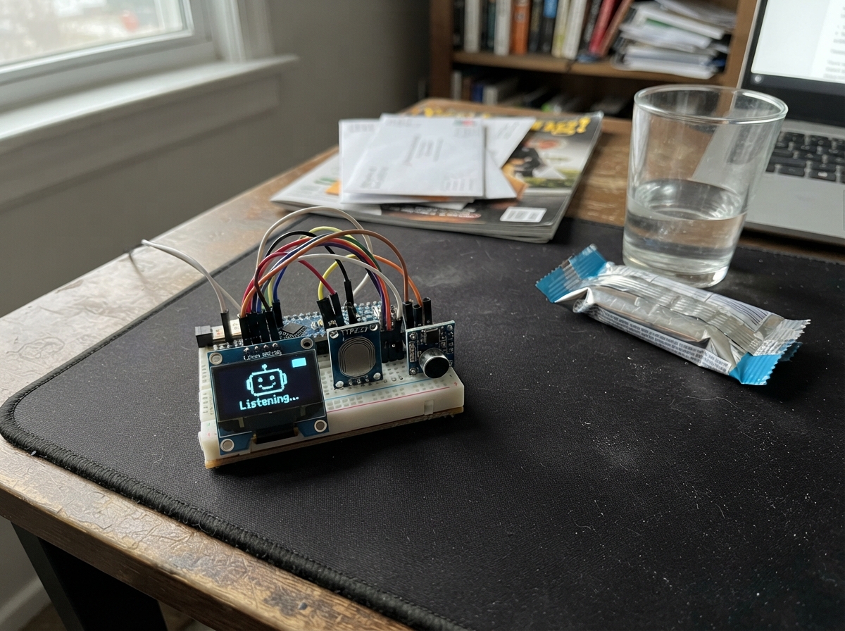
Voice-Interactive Desk Buddy brings offline voice recognition to your desk using an ESP32 microcontroller, a capacitive touch sensor, and an AI-Thinker VC-02 voice module. The project displays voice commands and system status on a 1.3-inch OLED screen, letting you interact with the device through touch and spoken input without relying on cloud services.
This guide provides a complete parts list, wiring diagram for all seven connections, step-by-step assembly instructions, and Arduino firmware with voice packet handling and display management. Builders will learn how to integrate multiple communication protocols (SPI for the display, serial for the voice module) and implement debounced touch sensing on a single microcontroller.
Wiring diagram

Gather all the parts
Assemble it in 5 steps
1. Place the parts with USB unplugged
Put the ESP32 DevKit, VC-02, seven-pin OLED, and touch board on a breadboard or desk-project base. Leave the ESP32 USB cable unplugged while making every wire connection.
- Keep the VC-02 microphone facing toward where you will speak from.
- Do not connect or remove wires while USB power is connected; a misplaced wire can short the board.
2. Wire the seven-pin screen
Follow the labels printed on your screen: OLED GND → ESP32 GND (ground), VCC → ESP32 3V3 (power), SCK → GPIO18 (screen clock), SDA → GPIO23 (screen data), RES → GPIO25 (screen reset), DC → GPIO26 (tells the screen whether data is text or a command), and CS → GPIO32 (selects this screen).
- On this seven-pin screen, SDA means SPI data; it does not connect to GPIO21.
- The labels in your photo read left to right: GND, VCC, SCK, SDA, RES, DC, CS.
- Make sure VCC and GND are not swapped — swapped power can damage the screen.
- Use the ESP32 3V3 pin, not VIN/5V, for the OLED.
3. Wire the touch pad
Connect TTP223 VCC → ESP32 3V3 (power), TTP223 GND → ESP32 GND (ground), and TTP223 SIG → GPIO27 (touch signal).
- Use the three-pin header labelled VCC, GND, and SIG.
- Do not power the touch module from 5V because its signal could rise above the ESP32’s safe 3.3V input level.
4. Wire the voice module directly
Connect VC-02 VCC → ESP32 VIN/5V (power), VC-02 GND → ESP32 GND (ground), VC-02 TX1 → ESP32 GPIO16 (voice data into the ESP32), and VC-02 RX1 → ESP32 GPIO17 (voice data out to the VC-02).
- TX and RX cross over: the VC-02 TX1 pin goes to ESP32 GPIO16, while ESP32 GPIO17 goes to VC-02 RX1.
- Use the VC-02 pins marked TX1 and RX1, not its log-output pin.
- All parts must share GND or the voice messages and touch signal will be unreliable.
- Do not connect any VC-02 pin other than TX1 or RX1 to an ESP32 GPIO unless its label and voltage are known.
5. Power and test the desk buddy
Check each wire once more, then plug the ESP32 into USB. The screen should show AI DESK BUDDY and “Touch to wake.” Touch the pad once, then speak one of the commands loaded into your VC-02.
- The display shows received command bytes, helping you identify each factory voice command before adding its desk-buddy action.
- If the screen stays blank, unplug USB first and recheck all seven screen wires against their printed labels.
Review all connections
1. Connections between "touch_1" and "ESP32"
2. Connections between "oled_1" and "ESP32"
3. Connections between "vc02_1" and "ESP32"
Deploy the firmware
#include <Arduino.h>
#include <SPI.h>
#include <Adafruit_GFX.h>
#include <Adafruit_SSD1306.h>

void drawScreen();
String hexByte(uint8_t value);
void showVoicePacket();

constexpr int VC02_RX_PIN = 16;
constexpr int VC02_TX_PIN = 17;
constexpr int TOUCH_PIN = 27;
constexpr int OLED_SCK_PIN = 18;
constexpr int OLED_MOSI_PIN = 23;
constexpr int OLED_RESET_PIN = 25;
constexpr int OLED_DC_PIN = 26;
constexpr int OLED_CS_PIN = 32;
constexpr unsigned long TOUCH_DEBOUNCE_MS = 40;
constexpr unsigned long MESSAGE_HOLD_MS = 3500;

Adafruit_SSD1306 display(128, 64, &SPI, OLED_DC_PIN, OLED_RESET_PIN, OLED_CS_PIN);
HardwareSerial voiceSerial(2);

bool lastTouchReading = false;
bool touchState = false;
unsigned long touchChangedAt = 0;
unsigned long messageShownAt = 0;
String statusLine = "Ready";
String packetLine = "Touch to wake";

void drawScreen() {
  display.clearDisplay();
  display.setTextColor(SSD1306_WHITE);
  display.setTextSize(1);
  display.setCursor(0, 0);
  display.println(F("AI DESK BUDDY"));
  display.drawFastHLine(0, 11, 128, SSD1306_WHITE);
  display.setCursor(0, 18);
  display.print(F("Status: "));
  display.println(statusLine);
  display.setCursor(0, 34);
  display.println(F("Voice command:"));
  display.setCursor(0, 47);
  display.println(packetLine);
  display.display();
}

String hexByte(uint8_t value) {
  const char hex[] = "0123456789ABCDEF";
  String text;
  text += hex[(value >> 4) & 0x0F];
  text += hex[value & 0x0F];
  return text;
}

void showVoicePacket() {
  String bytes;
  unsigned long lastByteAt = millis();
  while (millis() - lastByteAt < 35) {
    while (voiceSerial.available()) {
      uint8_t value = static_cast<uint8_t>(voiceSerial.read());
      if (bytes.length() > 0) bytes += ' ';
      bytes += hexByte(value);
      lastByteAt = millis();
    }
    delay(1);
  }

  if (bytes.length() > 0) {
    statusLine = "Command received";
    packetLine = bytes.substring(0, 20);
    messageShownAt = millis();
    drawScreen();
    Serial.print(F("VC-02 packet: "));
    Serial.println(bytes);
  }
}

void setup() {
  Serial.begin(115200);
  pinMode(TOUCH_PIN, INPUT);
  SPI.begin(OLED_SCK_PIN, -1, OLED_MOSI_PIN, OLED_CS_PIN);
  if (!display.begin(SSD1306_SWITCHCAPVCC)) {
    Serial.println(F("SSD1306 not found"));
    for (;;) delay(10);
  }
  voiceSerial.begin(115200, SERIAL_8N1, VC02_RX_PIN, VC02_TX_PIN);
  drawScreen();
}

void loop() {
  bool reading = digitalRead(TOUCH_PIN) == HIGH;
  if (reading != lastTouchReading) {
    touchChangedAt = millis();
    lastTouchReading = reading;
  }

  if ((millis() - touchChangedAt) >= TOUCH_DEBOUNCE_MS && reading != touchState) {
    touchState = reading;
    if (touchState) {
      statusLine = "Hello! Listening...";
      packetLine = "Speak to VC-02";
      messageShownAt = millis();
      drawScreen();
    }
  }

  if (voiceSerial.available()) showVoicePacket();

  if (statusLine != "Ready" && millis() - messageShownAt >= MESSAGE_HOLD_MS) {
    statusLine = "Ready";
    packetLine = "Touch to wake";
    drawScreen();
  }
}
Remix this project
Make it yours in one click
Open a full copy of this project in your own Schematik workspace — diagram, code, parts, and assembly steps included. Swap the sensor, add features, or redesign the whole thing with AI. The author's original stays untouched.