Community project
VW T1 RPM LED Strip
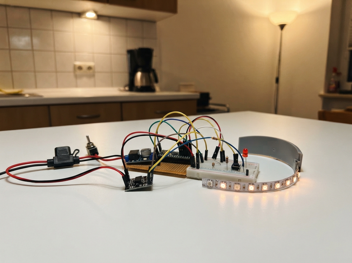
This project transforms a VW T1 into a modern ride with a real-time RPM display using a 49-LED WS2812B strip that lights up as engine speed increases. The guide covers wiring a tachometer signal adapter to an Arduino Uno, conditioning the ignition signal through an optocoupler for safety, and programming smooth RPM visualization with a shift light that activates at high revs.
Builders will receive a complete wiring diagram, parts list with fuse and voltage specifications, step-by-step assembly instructions, and Arduino firmware that reads engine pulses, filters noise, and drives the LED strip with color-coded RPM zones. The project includes a push button for display modes and a separate shift-light LED to alert drivers when it's time to shift.
Wiring diagram
Gather all the parts
Assemble it in 7 steps
1. Set the 5-volt converter before attaching electronics
With the car supply disconnected, use a meter to set buck_5v to exactly 5.0 V. Connect the fused switched vehicle positive wire to VIN+ and the vehicle return wire to VIN−. Do not connect the Nano or LEDs until this measurement is correct.
- More than 5 V from the converter can damage the Nano, the PC817 output side, and the LED strip.
2. Make the shared 5-volt supply
Connect buck_5v VOUT+ to Nano 5V and LED-strip VCC (power). Connect buck_5v VOUT− to Nano GND and LED-strip GND (ground). Feed the same 5 V and GND to pc817_module VCC and GND (power and ground).
- If LEDs at the far end later become dim or change colour, run an additional 5 V and GND pair to that far end of the strip.
3. Fit the capacitor at the strip input
Connect bulk_capacitor directly beside the LED-strip input: the positive lead marked + goes to LED-strip 5 V (power), and the striped negative lead marked − goes to LED-strip GND (ground).
- Do not swap the capacitor leads — a reversed electrolytic capacitor can heat up and fail.
4. Connect the 49 LED data wire
Connect Nano D6 to one end of data_resistor (data), then connect its other end to DATA or DIN on the first LED at the arrow-input end of led_strip (data). The resistor value is 392 Ω and should sit near the first LED.
- The arrow on the strip points away from the DIN end; connecting to DOUT will not work.
5. Connect the button and separate shift light
Connect mode_button between Nano D4 and GND (button signal). Connect Nano D9 to shift_resistor, then to the long anode leg of shift_led (light signal); connect the short cathode leg of shift_led to GND (ground).
- Keep the 700 Ω resistor in series with the shift LED — connecting that LED directly to D9 can damage the Nano pin.
6. Connect the protected ignition-signal chain
Connect Zündspule Klemme 1 (−) only to tach_adapter_lv KLEMME 1 IN (ignition signal). Connect tach_adapter_lv TACH OUT 12V to pc817_module INPUT+ (12-V signal), and tach_adapter_lv GND to pc817_module INPUT− (signal return). On the safe side, pc817_module OUT goes to Nano D2 (speed signal).
- Never connect Klemme 1 directly to PC817 INPUT+ or INPUT− — the adapter must remain between the ignition coil and the optocoupler.
7. Test the display, then test the engine signal
First power the Nano from USB only with the vehicle ignition signal disconnected. Confirm the start animation, the moving standby light, the D4 button, and the D9 shift LED. Then disconnect USB before using the vehicle 5-V supply, start the engine, and compare the displayed speed with the known analogue tachometer.
- Do not connect USB and the vehicle 5-V supply together unless your supply wiring prevents power flowing back into the computer USB port.
Review all connections
1. Connections between "vehicle_power" and "Arduino"
2. Connections between "buck_5v" and "Arduino"
3. Connections between "pc817_module" and "Arduino"
4. Connections between "led_strip" and "Arduino"
5. Connections between "mode_button" and "Arduino"
6. Connections between "shift_resistor" and "Arduino"
7. Connections between "shift_led" and "Arduino"
8. Connections between "bulk_capacitor" and "Arduino"
9. Connections between "tach_adapter_lv" and "Arduino"
10. Connections between "data_resistor" and "Arduino"
Deploy the firmware
#include <FastLED.h>

// ============================================================
// HARDWARE
// ============================================================
constexpr byte LED_PIN = 6;
constexpr byte PULSE_PIN = 2;
constexpr byte BUTTON_PIN = 4;
constexpr byte SHIFT_LED_PIN = 9;
constexpr byte NUM_LEDS = 49;

// Dein alter Streifen war mit NEO_RGB eingestellt. Falls Grün und Rot
// vertauscht sind, RGB hier auf GRB ändern.
CRGB leds[NUM_LEDS];

// ============================================================
// ZÜNDSIGNAL UND DREHZAHL
// ============================================================
constexpr float PULSES_PER_REVOLUTION = 2.0f;
constexpr unsigned long MIN_PULSE_INTERVAL_US = 2000UL;
constexpr unsigned long RPM_TIMEOUT_MS = 300UL;
constexpr byte RPM_SAMPLES = 4;

volatile unsigned long lastAcceptedPulseUs = 0;
volatile unsigned long pulseIntervalUs = 0;
volatile bool haveNewInterval = false;

float rpm = 0.0f;
float shownRpm = 0.0f;
float rpmSamples[RPM_SAMPLES] = {0};
byte sampleIndex = 0;
byte sampleCount = 0;
unsigned long lastValidPulseMs = 0;

// ============================================================
// ANZEIGE, PEAK UND SCHALTBLITZ
// ============================================================
constexpr int RPM_FIRST_LED = 1000;
constexpr int RPM_PER_LED = 250;
constexpr int RPM_SHIFT_START = 4300;
constexpr int RPM_SHIFT_END = 4500;
constexpr unsigned long PEAK_HOLD_TIME = 1500UL;
constexpr unsigned long PEAK_FADE_TIME = 1000UL;
constexpr unsigned long SHIFT_FLASH_INTERVAL = 80UL;

bool pointMode = false;       // false = Balken, true = einzelner Punkt
int peakLed = -1;
unsigned long peakHoldStart = 0;
bool shiftFlashState = false;
unsigned long lastShiftFlashMs = 0;

// ============================================================
// TASTER UND HELLIGKEIT
// ============================================================
const byte brightnessValues[] = {30, 64, 150, 255};
byte brightnessLevel = 1;
constexpr unsigned long DEBOUNCE_MS = 30UL;
constexpr unsigned long LONG_PRESS_MS = 500UL;

bool buttonLastReading = HIGH;
bool buttonStableState = HIGH;
bool buttonPressed = false;
unsigned long lastDebounceMs = 0;
unsigned long buttonPressStartMs = 0;

enum FeedbackType { FEEDBACK_NONE, FEEDBACK_MODE, FEEDBACK_BRIGHTNESS };
FeedbackType feedbackType = FEEDBACK_NONE;
bool feedbackActive = false;
unsigned long feedbackStartMs = 0;
constexpr unsigned long MODE_FEEDBACK_TIME = 150UL;
constexpr unsigned long BRIGHTNESS_FEEDBACK_TIME = 600UL;

unsigned long lastDisplayFrameMs = 0;

// Der Streifen ist mechanisch umgekehrt eingebaut: logische LED 0 ist
// daher die physische letzte LED.
void logicalPixel(byte logicalIndex, const CRGB &color) {
  leds[NUM_LEDS - 1 - logicalIndex] = color;
}

CRGB zoneColor(byte logicalIndex) {
  if (logicalIndex <= 23) return CRGB(0, 255, 0);
  if (logicalIndex <= 37) return CRGB(255, 55, 0);
  return CRGB(255, 0, 0);
}

void countPulse() {
  const unsigned long now = micros();
  const unsigned long gap = now - lastAcceptedPulseUs;

  // Störflanken näher als 2 ms werden ignoriert und verschieben den
  // Bezugspunkt für den nächsten echten Impuls nicht.
  if (lastAcceptedPulseUs == 0 || gap >= MIN_PULSE_INTERVAL_US) {
    if (lastAcceptedPulseUs != 0) {
      pulseIntervalUs = gap;
      haveNewInterval = true;
    }
    lastAcceptedPulseUs = now;
  }
}

int mappedLedCount(float value) {
  if (value < RPM_FIRST_LED) return 0;
  int count = 1 + int((value - RPM_FIRST_LED) / RPM_PER_LED);
  if (count < 0) return 0;
  if (count > NUM_LEDS) return NUM_LEDS;
  return count;
}

void updateRpm(unsigned long now) {
  noInterrupts();
  const bool gotInterval = haveNewInterval;
  const unsigned long interval = pulseIntervalUs;
  haveNewInterval = false;
  interrupts();

  if (gotInterval && interval > 0) {
    const float candidate = 60000000.0f / (interval * PULSES_PER_REVOLUTION);
    const bool plausibleRange = candidate >= 100.0f && candidate <= 8000.0f;
    const bool plausibleChange = rpm < 500.0f ||
      (candidate > rpm * 0.5f && candidate < rpm * 2.0f);

    if (plausibleRange && plausibleChange) {
      rpmSamples[sampleIndex] = candidate;
      sampleIndex = (sampleIndex + 1) % RPM_SAMPLES;
      if (sampleCount < RPM_SAMPLES) sampleCount++;

      float sum = 0.0f;
      for (byte i = 0; i < sampleCount; i++) sum += rpmSamples[i];
      rpm = sum / sampleCount;
      lastValidPulseMs = now;
    }
  }

  if (now - lastValidPulseMs > RPM_TIMEOUT_MS) {
    rpm = 0.0f;
    shownRpm = 0.0f;
    sampleIndex = 0;
    sampleCount = 0;
    for (byte i = 0; i < RPM_SAMPLES; i++) rpmSamples[i] = 0.0f;
    peakLed = -1;
  } else if (rpm > 0.0f) {
    const float factor = rpm > shownRpm ? 0.35f : 0.45f;
    shownRpm += (rpm - shownRpm) * factor;
  }
}

void startModeFeedback() {
  feedbackActive = true;
  feedbackType = FEEDBACK_MODE;
  feedbackStartMs = millis();
  fill_solid(leds, NUM_LEDS, CRGB(40, 40, 40));
  FastLED.show();
}

void startBrightnessFeedback() {
  feedbackActive = true;
  feedbackType = FEEDBACK_BRIGHTNESS;
  feedbackStartMs = millis();
  FastLED.clear();
  const byte ledsToLight = min(byte(NUM_LEDS), byte((brightnessLevel + 1) * 3));
  for (byte i = 0; i < ledsToLight; i++) logicalPixel(i, CRGB(0, 0, 255));
  FastLED.show();
}

void updateButton(unsigned long now) {
  const bool reading = digitalRead(BUTTON_PIN);
  if (reading != buttonLastReading) lastDebounceMs = now;

  if (now - lastDebounceMs > DEBOUNCE_MS && reading != buttonStableState) {
    buttonStableState = reading;
    if (buttonStableState == LOW) {
      buttonPressed = true;
      buttonPressStartMs = now;
    } else if (buttonPressed) {
      buttonPressed = false;
      const unsigned long pressedFor = now - buttonPressStartMs;
      if (pressedFor < LONG_PRESS_MS) {
        pointMode = !pointMode;
        startModeFeedback();
      } else {
        brightnessLevel = (brightnessLevel + 1) % 4;
        FastLED.setBrightness(brightnessValues[brightnessLevel]);
        startBrightnessFeedback();
      }
    }
  }
  buttonLastReading = reading;
}

void updateFeedback(unsigned long now) {
  if (!feedbackActive) return;
  const unsigned long duration = feedbackType == FEEDBACK_MODE
    ? MODE_FEEDBACK_TIME : BRIGHTNESS_FEEDBACK_TIME;
  if (now - feedbackStartMs >= duration) {
    feedbackActive = false;
    feedbackType = FEEDBACK_NONE;
  }
}

void drawStandby(unsigned long now) {
  static byte head = 0;
  static unsigned long lastMoveMs = 0;
  if (now - lastMoveMs >= 50UL) {
    head = (head + 1) % NUM_LEDS;
    lastMoveMs = now;
  }

  FastLED.clear();
  for (byte tail = 0; tail < 5; tail++) {
    int position = int(head) - tail;
    if (position < 0) position += NUM_LEDS;
    logicalPixel(position, CRGB(255 / (tail + 1), 70 / (tail + 1), 15 / (tail + 1)));
  }
  FastLED.show();

  // Langsame PWM-Atemfunktion für die separate LED an D9.
  const unsigned long phase = now % 2040UL;
  const byte level = phase < 1020UL ? phase / 4 : (2040UL - phase) / 4;
  analogWrite(SHIFT_LED_PIN, level);
}

void drawRpm(unsigned long now) {
  const int lit = mappedLedCount(shownRpm);
  const int currentLed = lit - 1;

  if (currentLed >= peakLed) {
    peakLed = currentLed;
    peakHoldStart = now;
  }

  const bool inShiftWindow = shownRpm >= RPM_SHIFT_START && shownRpm < RPM_SHIFT_END;
  if (inShiftWindow && now - lastShiftFlashMs >= SHIFT_FLASH_INTERVAL) {
    lastShiftFlashMs = now;
    shiftFlashState = !shiftFlashState;
  }

  if (inShiftWindow) {
    if (shiftFlashState) fill_solid(leds, NUM_LEDS, CRGB::Red);
    else FastLED.clear();
    analogWrite(SHIFT_LED_PIN, shiftFlashState ? 255 : 0);
    FastLED.show();
    return;
  }

  shiftFlashState = false;
  analogWrite(SHIFT_LED_PIN, 0);
  FastLED.clear();

  if (pointMode) {
    if (currentLed >= 0) logicalPixel(currentLed, zoneColor(currentLed));
  } else {
    for (byte i = 0; i < lit; i++) logicalPixel(i, zoneColor(i));
  }

  // Peak bleibt 1,5 s stehen und wird danach innerhalb 1 s ausgeblendet.
  if (peakLed >= 0 && peakLed > currentLed) {
    const unsigned long elapsed = now - peakHoldStart;
    if (elapsed < PEAK_HOLD_TIME + PEAK_FADE_TIME) {
      if (elapsed < PEAK_HOLD_TIME) {
        logicalPixel(peakLed, CRGB(0, 255, 200));
      } else {
        const float remaining = 1.0f - float(elapsed - PEAK_HOLD_TIME) / PEAK_FADE_TIME;
        logicalPixel(peakLed, CRGB(0, byte(255 * remaining), byte(200 * remaining)));
      }
    } else {
      peakLed = -1;
    }
  } else if (peakLed <= currentLed) {
    peakLed = -1;
  }

  FastLED.show();
}

void startupAnimation() {
  const CRGB colors[] = {CRGB::Green, CRGB(255, 55, 0), CRGB::Red};
  FastLED.setBrightness(190);

  for (byte colorIndex = 0; colorIndex < 3; colorIndex++) {
    FastLED.clear();
    for (byte i = 0; i < NUM_LEDS; i++) {
      logicalPixel(i, colors[colorIndex]);
      FastLED.show();
      delay(12);
    }
    delay(100);
  }

  for (byte flash = 0; flash < 2; flash++) {
    fill_solid(leds, NUM_LEDS, CRGB::Green);
    analogWrite(SHIFT_LED_PIN, 255);
    FastLED.show();
    delay(120);
    FastLED.clear();
    analogWrite(SHIFT_LED_PIN, 0);
    FastLED.show();
    delay(120);
  }

  FastLED.clear();
  FastLED.setBrightness(brightnessValues[brightnessLevel]);
  FastLED.show();
}

void setup() {
  pinMode(PULSE_PIN, INPUT_PULLUP);
  pinMode(BUTTON_PIN, INPUT_PULLUP);
  pinMode(SHIFT_LED_PIN, OUTPUT);
  analogWrite(SHIFT_LED_PIN, 0);

  FastLED.addLeds<WS2812B, LED_PIN, RGB>(leds, NUM_LEDS);
  FastLED.setBrightness(brightnessValues[brightnessLevel]);
  FastLED.clear(true);
  startupAnimation();

  attachInterrupt(digitalPinToInterrupt(PULSE_PIN), countPulse, FALLING);
  lastValidPulseMs = millis();
}

void loop() {
  const unsigned long now = millis();
  updateButton(now);
  updateRpm(now);
  updateFeedback(now);

  // 20 Bilder pro Sekunde für die bewegte Standby-Anzeige; die Messung und
  // der Taster laufen weiterhin in jeder Schleifenrunde weiter.
  if (!feedbackActive && now - lastDisplayFrameMs >= 50UL) {
    lastDisplayFrameMs = now;
    if (shownRpm < 50.0f) drawStandby(now);
    else drawRpm(now);
  }
  delay(1);
}
Remix this project
Make it yours in one click
Open a full copy of this project in your own Schematik workspace — diagram, code, parts, and assembly steps included. Swap the sensor, add features, or redesign the whole thing with AI. The author's original stays untouched.
Related projects
Solar Clap-Controlled Follow-Me Home
Arduino · October 19, 2026Jella Mae Lhyzelle Rodillo
Solar Light Tracker
Arduino · October 19, 2026kelleyriverarodriguez1969
RC Kontrollü Balıkçı Gemisi
Arduino · October 19, 2026hasan azmi hacıfettahoğlu