Community project
Weekday Break Bell Scheduler
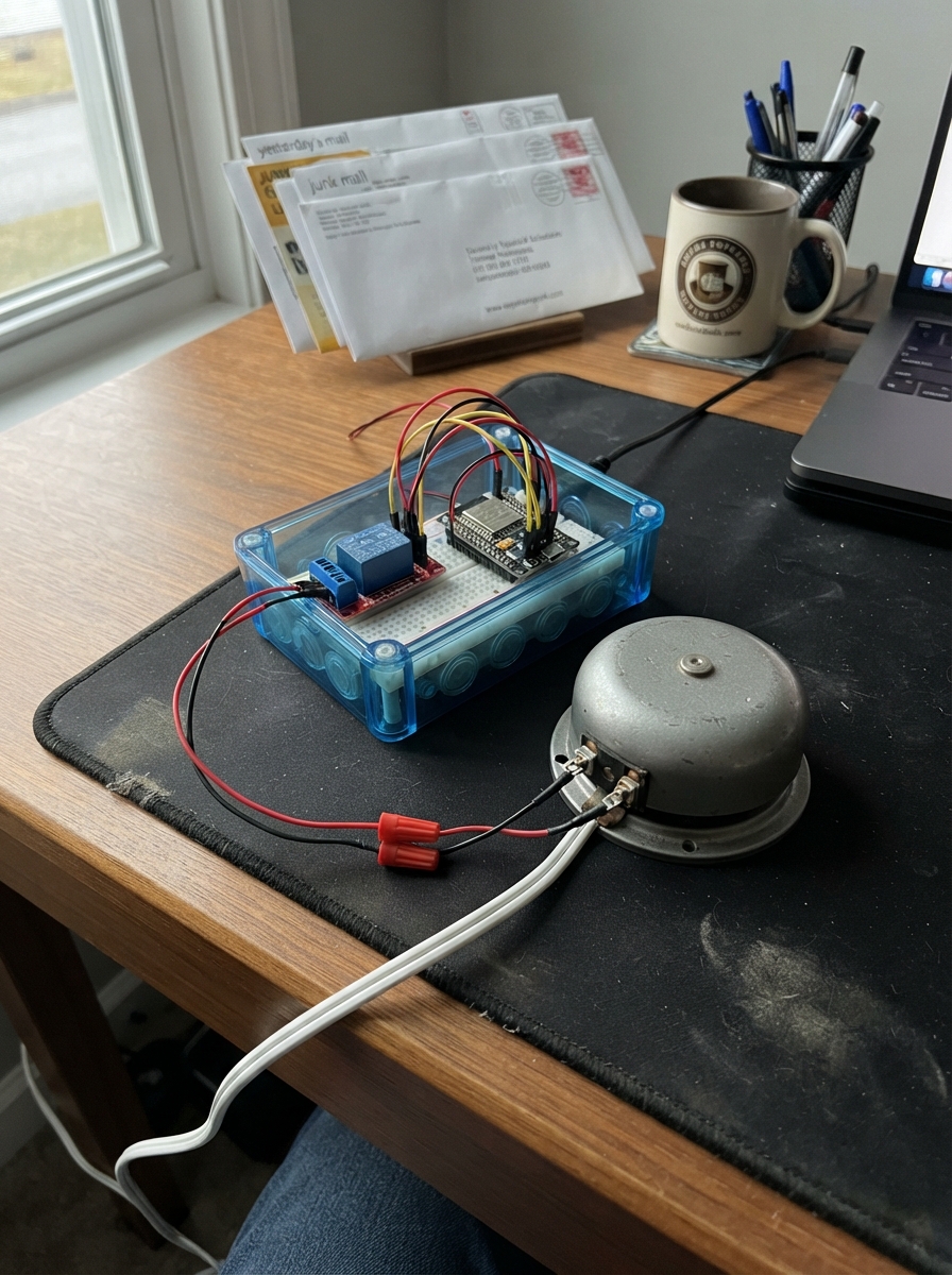
The Weekday Break Bell Scheduler uses an ESP32 to ring a 24 V AC bell at preset times during school days. It connects to Wi-Fi to sync the current time, then automatically triggers the bell at eight scheduled intervals throughout weekdays—perfect for signaling class changes, breaks, or lunch periods without manual intervention.
This guide provides a complete wiring diagram showing how to connect the ESP32 to the opto-isolated relay module and integrate it into your existing bell circuit, a full parts list, ready-to-deploy firmware with customizable bell times, and step-by-step assembly instructions. Simply add your Wi-Fi credentials, upload the code, and the system will keep accurate time and ring on schedule.
Wiring diagram

Gather all the parts
Assemble it in 5 steps
1. Keep the bell supply separate
Turn off the existing 24 V AC bell transformer before touching its wires. This project uses only the transformer’s already-isolated 24 V output; do not connect the ESP32, relay input pins, or breadboard to wall-power wiring.
- Find the two low-voltage wires that normally feed the 24 V AC bell.
- Use an enclosure and strain relief for the relay-contact and bell wiring.
- Do not work on building mains wiring yourself: an incorrect connection can cause electric shock, fire, or damage. Have a qualified installer make or alter any wall-power connection.
2. Connect the ESP32 to the relay control side
With USB unplugged, connect relay_1 VCC to the ESP32 3V3 pin (power), relay_1 GND to an ESP32 GND pin (ground), and relay_1 IN to ESP32 GPIO25 (signal). These three wires are the safe low-voltage control side.
- Use three different wire colors; for example red for 3V3, black for GND, and yellow for GPIO25.
- Check the relay board label carefully: VCC and GND must not be swapped — swapped power can damage the relay module.
- Use only a relay module whose input works from 3.3 V and whose COM/NO contacts are rated for at least 30 V AC and more current than the bell uses.
3. Put the relay contact in the bell wire
Leave one 24 V AC transformer lead connected directly to one terminal of bell_1. Route the other transformer lead to relay_1 COM (switched power), then connect relay_1 NO to the remaining bell_1 terminal (switched power). The normally-open contact keeps the bell off until the ESP32 rings it.
- COM and NO are simple switch contacts, so the 24 V AC wires may be connected either way around between those two terminals.
- Use insulated crimp terminals or a proper terminal block; gently tug each wire to make sure it is clamped.
- Never put 24 V AC on relay_1 VCC, GND, IN, the ESP32, or a breadboard — it can permanently damage the board and create a shock hazard.
4. Add your Wi-Fi name and password
In the two clearly marked lines near the top of the project code, replace YOUR_WIFI_NAME and YOUR_WIFI_PASSWORD with the Wi-Fi network name and password the ESP32 should use. Keep the quotation marks around each value.
- Use a 2.4 GHz Wi-Fi network; a standard ESP32 cannot join a 5 GHz-only network.
- The clock gets New York time from time.nist.gov after it joins Wi-Fi, including seasonal clock changes.
- Do not publish or share the project code after putting a real Wi-Fi password in it.
5. Power and deploy the clock
Recheck that the relay-control wires and the 24 V AC bell wires are on their separate relay terminals. Plug the ESP32 into USB, then press Deploy in Schematik. At the next weekday schedule time, the relay closes for five seconds and the bell rings.
- A relay module often makes a soft click during the five-second bell period.
- The schedule is Monday through Friday at 8:00, 10:00, 10:15, 12:00, 12:30, 2:00, 2:15, and 4:30 New York time.
- If the relay stays energized when the ESP32 starts, unplug USB immediately; the particular module may use the opposite input logic level and should be checked before leaving it connected to the bell.
Review all connections
1. Connections between "relay_1" and "ESP32"
2. Connections between "bell_1" and "ESP32"
Deploy the firmware
#include <Arduino.h>
#include <WiFi.h>
#include <time.h>

// Replace these two placeholders before pressing Deploy.

// Forward declarations
void setRelay(bool on);
void connectWiFiIfNeeded();
bool isScheduledTime(const tm &localTime, int &slot);

const char *WIFI_SSID = "YOUR_WIFI_NAME";
const char *WIFI_PASSWORD = "YOUR_WIFI_PASSWORD";

constexpr int RELAY_PIN = 25;
constexpr bool RELAY_ACTIVE_LOW = true;  // Typical opto-isolated relay module.
constexpr unsigned long RING_DURATION_MS = 5000;

bool relayOn = false;
unsigned long ringStartedAt = 0;
long lastRingKey = -1;
unsigned long lastWifiAttemptAt = 0;

const int bellHours[] = {8, 10, 10, 12, 12, 14, 14, 16};
const int bellMinutes[] = {0, 0, 15, 0, 30, 0, 15, 30};
constexpr size_t BELL_COUNT = sizeof(bellHours) / sizeof(bellHours[0]);

void setRelay(bool on) {
  relayOn = on;
  digitalWrite(RELAY_PIN, (on == RELAY_ACTIVE_LOW) ? LOW : HIGH);
}

void connectWiFiIfNeeded() {
  if (WiFi.status() == WL_CONNECTED) {
    return;
  }

  if (millis() - lastWifiAttemptAt < 30000) {
    return;
  }

  lastWifiAttemptAt = millis();
  WiFi.disconnect();
  WiFi.begin(WIFI_SSID, WIFI_PASSWORD);
}

bool isScheduledTime(const tm &localTime, int &slot) {
  // tm_wday: Sunday = 0, Monday = 1, ... Saturday = 6.
  if (localTime.tm_wday < 1 || localTime.tm_wday > 5) {
    return false;
  }

  for (size_t i = 0; i < BELL_COUNT; ++i) {
    if (localTime.tm_hour == bellHours[i] && localTime.tm_min == bellMinutes[i]) {
      slot = static_cast<int>(i);
      return true;
    }
  }
  return false;
}

void setup() {
  pinMode(RELAY_PIN, OUTPUT);
  setRelay(false);  // Keep the bell off while the clock starts.

  WiFi.mode(WIFI_STA);
  connectWiFiIfNeeded();

  // New York time: Eastern Standard Time with US daylight-saving changes.
  configTzTime("EST5EDT,M3.2.0/2,M11.1.0/2", "time.nist.gov");
}

void loop() {
  connectWiFiIfNeeded();

  if (relayOn && millis() - ringStartedAt >= RING_DURATION_MS) {
    setRelay(false);
  }

  tm localTime;
  if (!getLocalTime(&localTime, 10)) {
    delay(50);
    return;
  }

  int slot = -1;
  if (isScheduledTime(localTime, slot)) {
    // A unique key prevents repeated ringing during the same scheduled minute.
    const long today = (localTime.tm_year + 1900L) * 1000L + localTime.tm_yday;
    const long ringKey = today * 10L + slot;
    if (!relayOn && ringKey != lastRingKey) {
      lastRingKey = ringKey;
      ringStartedAt = millis();
      setRelay(true);
    }
  }

  delay(50);
}
Remix this project
Make it yours in one click
Open a full copy of this project in your own Schematik workspace — diagram, code, parts, and assembly steps included. Swap the sensor, add features, or redesign the whole thing with AI. The author's original stays untouched.