Community project
Wi-Fi Piano Instrument
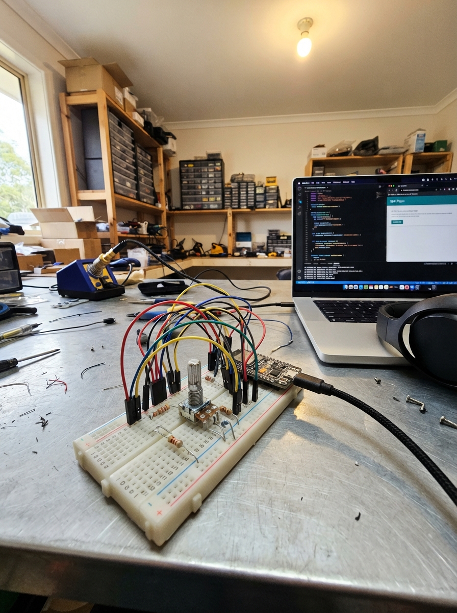
Build a Wi-Fi-connected piano instrument powered by an ESP32 that plays six notes across adjustable octaves. The device features physical pushbutton keys with LED feedback, an optional OLED display for status information, and a potentiometer knob to shift between octaves. Multiple users can play simultaneously through a web interface, with all interactions synchronized across connected devices.
This guide provides a complete wiring diagram, parts list, and step-by-step assembly instructions for breadboarding the piano on a 830-point board. The included firmware handles button debouncing, Wi-Fi connectivity, WebSocket communication, and note sequencing. Builders will learn how to integrate input controls, visual feedback, and wireless communication on the ESP32 platform.
Wiring diagram

Gather all the parts
Assemble it in 6 steps
1. Place the board and power rails
Put the ESP32-S3 Board (USB-C) beside the Breadboard 830 points. Use jumper wires to make one breadboard rail 3.3 V from a board 3V3 pin and another rail GND from a board G pin; every control and LED shares this ground.
- Keep the USB-C sockets accessible at the bottom of the board.
- Do not use the 5V pin for the potentiometer or OLED — 5 V on an ESP32-S3 signal can damage it.
2. Install the six piano buttons
Push each Tactile Pushbutton Switch Momentary 4pin 6×6×9mm across the breadboard centre gap in a row labelled C, D, E, F, G, A. On each switch, the two legs on one side are already joined inside the switch; use one side for the GPIO and the opposite side for GND: C → GPIO4 (signal) and GND (ground), D → GPIO5 (signal) and GND (ground), E → GPIO6 (signal) and GND (ground), F → GPIO7 (signal) and GND (ground), G → GPIO15 (signal) and GND (ground), A → GPIO16 (signal) and GND (ground).
- If pressing a button does nothing, turn it 90 degrees so it bridges the centre gap rather than placing both joined legs in one row.
- Do not connect two legs from the same side of a button to GPIO and GND — that makes a permanent short when no button is pressed.
3. Add the six LED note lights
For each LED, connect its long leg through its own Resistor 220Ω 1/4W to the named GPIO, and connect the short leg with the flat side of the LED body to GND: C red → GPIO8 (signal), D red → GPIO9 (signal), E yellow → GPIO10 (signal), F yellow → GPIO11 (signal), G green → GPIO12 (signal), A green → GPIO13 (signal).
- Each LED needs its own resistor; place the resistor in a separate breadboard row between GPIO and the long LED leg.
- Swapping an LED around normally prevents it lighting; omitting its resistor can damage the LED or board pin.
4. Wire the octave knob
Fit the 10kΩ Potentiometer, Linear, 20mm and its Potentiometer Knob Silver, small. Connect one outer terminal to 3V3 (power), the other outer terminal to GND (ground), and the centre terminal, called the wiper, to GPIO1 (signal).
- If turning clockwise lowers the octave, swap only the two outer wires; leave the centre wire on GPIO1.
- Never connect either potentiometer outer terminal to 5 V — GPIO1 can only accept 3.3 V.
5. Optionally connect the small screen
If your 0.96" OLED Display 128×64 I2C (Blue) is fitted and marked for 3.3 V operation, connect VCC → 3V3 (power), GND → GND (ground), SDA → GPIO17 (data), and SCL → GPIO18 (data). The piano works without this display.
- The display should show the access-point address, current note, and octave after it starts.
- Make sure VCC and GND are not swapped — swapped power can damage the screen.
6. Leave the buzzer disconnected
Do not wire the Passive Buzzer 3-12V AC, 2kHz in this version. GPIO14 is reserved for a future verified driver circuit, but no wire is connected to it. The board, buttons, LEDs, knob, OLED, and website work safely without it.
- The current build gives visual feedback only while the real buzzer type is verified.
- Do not connect this unverified buzzer directly to any ESP32-S3 GPIO; it could draw enough current to damage the board.
Review all connections
1. Connections between "button_c" and "ESP32"
2. Connections between "button_d" and "ESP32"
3. Connections between "button_e" and "ESP32"
4. Connections between "button_f" and "ESP32"
5. Connections between "button_g" and "ESP32"
6. Connections between "button_a" and "ESP32"
7. Connections between "potentiometer" and "ESP32"
8. Connections between "resistor_c" and "ESP32"
9. Connections between "led_c" and "ESP32"
10. Connections between "resistor_d" and "ESP32"
11. Connections between "led_d" and "ESP32"
12. Connections between "resistor_e" and "ESP32"
13. Connections between "led_e" and "ESP32"
14. Connections between "resistor_f" and "ESP32"
15. Connections between "led_f" and "ESP32"
16. Connections between "resistor_g" and "ESP32"
17. Connections between "led_g" and "ESP32"
18. Connections between "resistor_a" and "ESP32"
19. Connections between "led_a" and "ESP32"
20. Connections between "oled" and "ESP32"
Deploy the firmware
#include <Arduino.h>
#include <WiFi.h>
#include <Preferences.h>
#include <AsyncTCP.h>
#include <ESPAsyncWebServer.h>
#include <Wire.h>
#include <Adafruit_GFX.h>
#include <Adafruit_SSD1306.h>
#include "piano_page.h"

#define OLED_SCL 18

// The supplied buzzer is intentionally not connected: its electrical type is unverified.

struct PhysicalKey { bool stable = false, sampled = false; uint32_t changed = 0, order = 0; } physical[6];

struct BrowserClient { uint32_t id = 0, lastSeen = 0, order[6] = {}; } clients[8];


// Forward declarations
void sendState();
void updateOutputs();
void chooseActiveKey();
void stopAll();
void cancelDemo();
void scanButtons();
void updatePotentiometer();
void runDemo();
void beginAccessPoint();
void startHomeWiFi();
void handleMessage(AsyncWebSocketClient *client, void *arg, uint8_t *data, size_t len);
void onWsEvent(AsyncWebSocket *, AsyncWebSocketClient *client, AwsEventType type, void *arg, uint8_t *data, size_t len);

constexpr uint8_t POT_PIN = 1;
constexpr uint8_t BTN_PINS[6] = {4, 5, 6, 7, 15, 16};
constexpr uint8_t LED_PINS[6] = {8, 9, 10, 11, 12, 13};
constexpr uint8_t OLED_SDA = 17, OLED_SCL = 18;
constexpr uint32_t DEBOUNCE_MS = 25, CLIENT_TIMEOUT_MS = 4500;
constexpr char NOTE_NAMES[6] = {'C', 'D', 'E', 'F', 'G', 'A'};

AsyncWebServer server(80);
AsyncWebSocket ws("/ws");
Preferences prefs;
Adafruit_SSD1306 display(128, 64, &Wire, -1);
bool oledReady = false;


uint32_t sequenceNumber = 1;
uint8_t octave = 4;
int activeKey = -1;
int potFiltered = 0, lastPotControl = 0;
bool demoPlaying = false;
uint8_t demoStep = 0;
uint32_t demoNext = 0;
const int8_t demoNotes[] = {0,0,4,4,5,5,4, -1,3,3,2,2,1,1,0, -1, 4,4,3,3,2,2,1, -1,4,4,3,3,2,2,1};

BrowserClient *clientSlot(uint32_t id, bool create) {
  for (auto &c : clients) if (c.id == id) return &c;
  if (!create) return nullptr;
  for (auto &c : clients) if (c.id == 0) { c.id = id; c.lastSeen = millis(); return &c; }
  return nullptr;
}

void sendState() {
  char note[4] = "";
  if (activeKey >= 0) snprintf(note, sizeof(note), "%c%d", NOTE_NAMES[activeKey], octave);
  char json[100];
  snprintf(json, sizeof(json), "{\"note\":\"%s\",\"octave\":%u,\"demo\":%s}", note, octave, demoPlaying ? "true" : "false");
  ws.textAll(json);
}

void updateOutputs() {
  for (uint8_t i = 0; i < 6; ++i) digitalWrite(LED_PINS[i], i == activeKey ? HIGH : LOW);
  if (oledReady) {
    display.clearDisplay(); display.setTextColor(SSD1306_WHITE); display.setTextSize(1);
    display.setCursor(0, 0); display.println(WiFi.status() == WL_CONNECTED ? "Home Wi-Fi" : "Piano access point");
    display.println(WiFi.status() == WL_CONNECTED ? WiFi.localIP().toString() : WiFi.softAPIP().toString());
    display.setTextSize(2); display.setCursor(0, 28);
    if (activeKey >= 0) { display.print(NOTE_NAMES[activeKey]); display.print(octave); } else display.print("--");
    display.setTextSize(1); display.setCursor(0, 54); display.print("Octave "); display.print(octave);
    display.display();
  }
  sendState();
}

void chooseActiveKey() {
  int chosen = -1; uint32_t newest = 0;
  for (uint8_t i = 0; i < 6; ++i) if (physical[i].stable && physical[i].order >= newest) { newest = physical[i].order; chosen = i; }
  for (auto &c : clients) for (uint8_t i = 0; i < 6; ++i) if (c.order[i] >= newest) { newest = c.order[i]; chosen = i; }
  if (chosen != activeKey) { activeKey = chosen; updateOutputs(); }
}

void stopAll() {
  for (auto &p : physical) p.stable = false;
  for (auto &c : clients) for (uint8_t i = 0; i < 6; ++i) c.order[i] = 0;
  demoPlaying = false; activeKey = -1; updateOutputs();
}

void cancelDemo() { if (demoPlaying) { demoPlaying = false; demoStep = 0; } }

void scanButtons() {
  uint32_t now = millis();
  for (uint8_t i = 0; i < 6; ++i) {
    bool pressed = digitalRead(BTN_PINS[i]) == LOW;
    if (pressed != physical[i].sampled) { physical[i].sampled = pressed; physical[i].changed = now; }
    if (physical[i].stable != physical[i].sampled && now - physical[i].changed >= DEBOUNCE_MS) {
      physical[i].stable = physical[i].sampled;
      if (physical[i].stable) { cancelDemo(); physical[i].order = sequenceNumber++; }
      chooseActiveKey();
    }
  }
}

void updatePotentiometer() {
  static uint32_t lastRead = 0;
  if (millis() - lastRead < 40) return;
  lastRead = millis();
  int raw = analogRead(POT_PIN);
  potFiltered = potFiltered == 0 ? raw : (potFiltered * 7 + raw) / 8;
  if (abs(potFiltered - lastPotControl) < 130) return; // noise cannot steal website control
  lastPotControl = potFiltered;
  uint8_t next = potFiltered < 1250 ? 3 : (potFiltered > 2850 ? 5 : 4);
  if (next != octave) { octave = next; updateOutputs(); }
}

void runDemo() {
  if (!demoPlaying || millis() < demoNext) return;
  int8_t n = demoNotes[demoStep++];
  activeKey = n; updateOutputs();
  demoNext = millis() + (n < 0 ? 160 : 360);
  if (demoStep >= sizeof(demoNotes)) { demoPlaying = false; activeKey = -1; updateOutputs(); }
}

void beginAccessPoint() {
  uint64_t mac = ESP.getEfuseMac();
  char ssid[32]; snprintf(ssid, sizeof(ssid), "Schematik-Piano-%04X", (uint16_t)mac);
  WiFi.mode(WIFI_AP_STA);
  WiFi.softAP(ssid, "piano1234");
}

void startHomeWiFi() {
  prefs.begin("piano", true);
  String ssid = prefs.getString("ssid", ""), pass = prefs.getString("pass", "");
  prefs.end();
  if (ssid.length()) WiFi.begin(ssid.c_str(), pass.c_str());
}

void handleMessage(AsyncWebSocketClient *client, void *arg, uint8_t *data, size_t len) {
  AwsFrameInfo *info = (AwsFrameInfo *)arg;
  if (!info->final || info->index || info->len != len || len == 0 || len > 96) return;
  data[len] = 0;
  String m((char *)data); uint32_t id = client->id();
  BrowserClient *c = clientSlot(id, true); if (!c) return; c->lastSeen = millis();
  if (m.indexOf("\"t\":\"on\"") >= 0 || m.indexOf("\"t\":\"off\"") >= 0) {
    int p = m.indexOf("\"n\":"); if (p < 0) return; int n = m.substring(p + 4).toInt(); if (n < 0 || n > 5) return;
    cancelDemo();
    if (m.indexOf("\"t\":\"on\"") >= 0) c->order[n] = sequenceNumber++; else c->order[n] = 0;
    chooseActiveKey();
  } else if (m.indexOf("\"t\":\"octave\"") >= 0) {
    int p = m.indexOf("\"o\":"); if (p < 0) return; int o = m.substring(p + 4).toInt();
    if (o >= 3 && o <= 5 && o != octave) { octave = o; lastPotControl = potFiltered; updateOutputs(); }
  } else if (m.indexOf("\"t\":\"demo\"") >= 0) { stopAll(); demoPlaying = true; demoStep = 0; demoNext = millis(); }
  else if (m.indexOf("\"t\":\"stop\"") >= 0) stopAll();
  else if (m.indexOf("\"t\":\"state\"") >= 0) sendState();
}

void onWsEvent(AsyncWebSocket *, AsyncWebSocketClient *client, AwsEventType type, void *arg, uint8_t *data, size_t len) {
  if (type == WS_EVT_CONNECT) { clientSlot(client->id(), true); sendState(); }
  else if (type == WS_EVT_DATA) handleMessage(client, arg, data, len);
  else if (type == WS_EVT_DISCONNECT) { BrowserClient *c = clientSlot(client->id(), false); if (c) { *c = BrowserClient(); chooseActiveKey(); } }
}

void setup() {
  Serial.begin(115200); analogReadResolution(12);
  for (uint8_t i = 0; i < 6; ++i) { pinMode(BTN_PINS[i], INPUT_PULLUP); pinMode(LED_PINS[i], OUTPUT); digitalWrite(LED_PINS[i], LOW); }
  Wire.begin(OLED_SDA, OLED_SCL); oledReady = display.begin(SSD1306_SWITCHCAPVCC, 0x3C);
  beginAccessPoint(); startHomeWiFi();
  ws.onEvent(onWsEvent); server.addHandler(&ws);
  server.on("/", HTTP_GET, [](AsyncWebServerRequest *r) { r->send_P(200, "text/html", PAGE); });
  server.on("/setup", HTTP_POST, [](AsyncWebServerRequest *r) {
    if (!r->hasParam("ssid", true) || !r->hasParam("pass", true)) { r->send(400, "text/plain", "Enter a network name and password."); return; }
    String ssid = r->getParam("ssid", true)->value(), pass = r->getParam("pass", true)->value();
    if (ssid.length() > 32 || pass.length() > 63) { r->send(400, "text/plain", "Those details are too long."); return; }
    prefs.begin("piano", false); prefs.putString("ssid", ssid); prefs.putString("pass", pass); prefs.end();
    r->send(200, "text/plain", "Saved. Restart the board to try the home network; the Piano access point remains available if it cannot connect.");
  });
  server.begin(); updateOutputs();
}

void loop() {
  scanButtons(); updatePotentiometer(); runDemo(); ws.cleanupClients();
  uint32_t now = millis();
  for (auto &c : clients) if (c.id && now - c.lastSeen > CLIENT_TIMEOUT_MS) { c = BrowserClient(); chooseActiveKey(); }
}
Remix this project
Make it yours in one click
Open a full copy of this project in your own Schematik workspace — diagram, code, parts, and assembly steps included. Swap the sensor, add features, or redesign the whole thing with AI. The author's original stays untouched.