Community project
Wireless Volume Amplifier
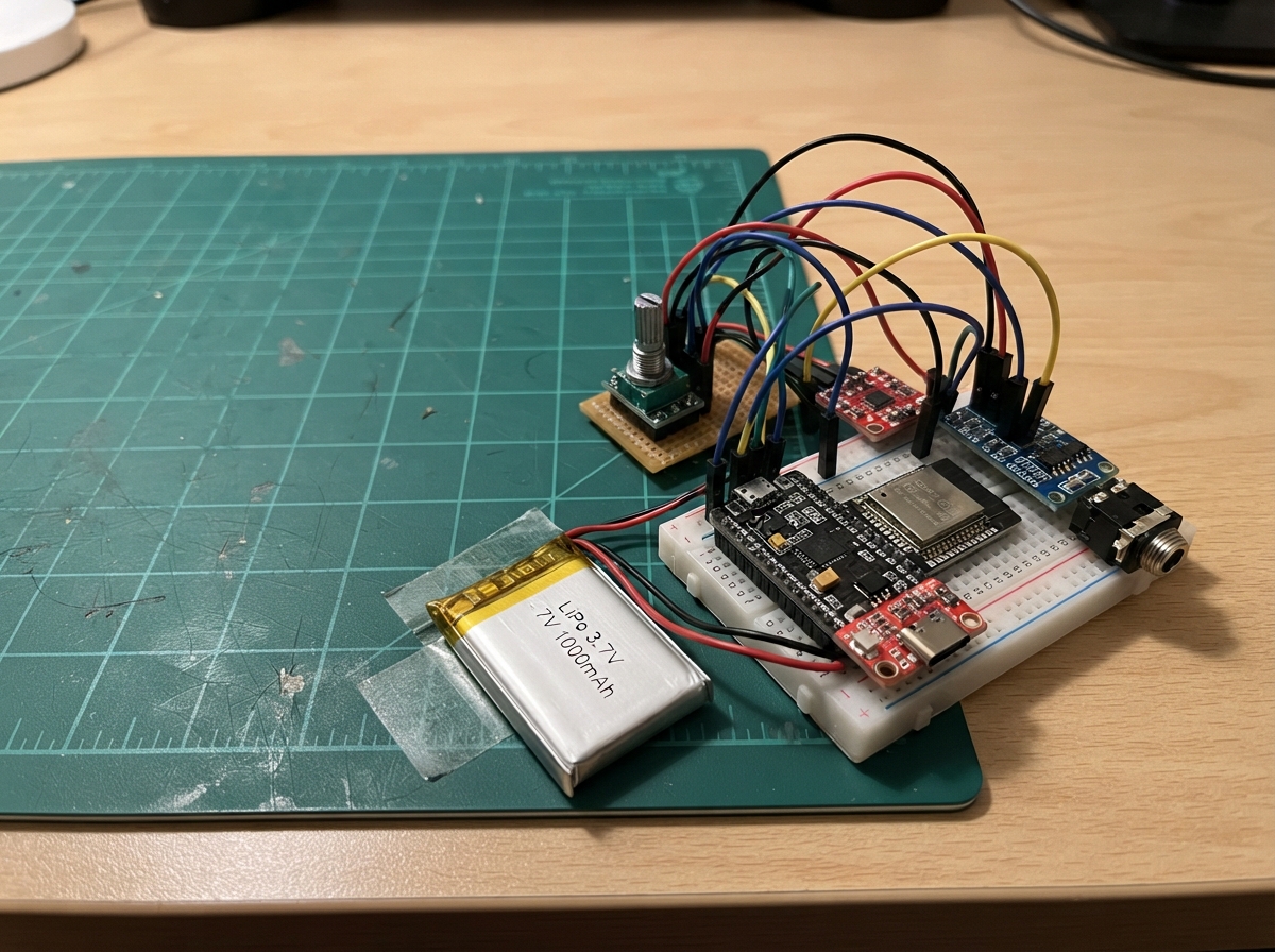
This wireless volume amplifier lets you control audio levels from across the room using a battery-powered rotary encoder remote. The system consists of a receiver box that sits between an audio source and amplifier, with a PT2258 digital volume controller managing the stereo signal path, while an ESP32-powered knob communicates wirelessly via ESP-NOW to adjust volume and mute.
The guide provides a complete wiring diagram, parts list, and step-by-step assembly instructions for building both the stationary receiver and the portable remote control. You'll flash a single firmware sketch to both ESP32 boards (configured via GPIO pin state), solder the audio jack and I2C logic converter, integrate the rotary encoder with debouncing, and set up safe LiPo battery charging with the bq25185 charger board.
Wiring diagram

Gather all the parts
Assemble it in 6 steps
1. Fit the receiver-box parts
Mount aux_input and aux_output in opposite sides of a non-metal enclosure, then mount volume_module, i2c_level_shifter, and the receiver ESP32 board so their USB socket remains reachable. Mark the input jack “SOURCE” and the output jack “SPEAKERS.”
- Use short shielded audio wire inside the box and keep it away from the ESP32 antenna end.
- Do not connect a passive speaker to this box: it provides only a safe line-level signal for speakers that already plug into wall power.
2. Wire the stereo audio path
Wire aux_input TIP to volume_module LIN (left audio), aux_input RING to volume_module RIN (right audio), and aux_input SLEEVE to volume_module AGND (audio ground). Then wire volume_module LOUT to aux_output TIP (left audio), ROUT to aux_output RING (right audio), and aux_output SLEEVE to volume_module GND (ground).
- On a 3.5 mm stereo jack, TIP is left, RING is right, and SLEEVE is the long ground contact.
- Do not swap the input and output jack labels; a source must feed the INPUT jack and powered speakers must connect to the OUTPUT jack.
3. Wire the receiver control board
Connect volume_module VCC to the receiver board’s 5V rail (power) and GND to GND (ground). Connect i2c_level_shifter HV to 5V (power), LV to 3V3 (power), and GND to GND (ground). Connect its LV1 to GPIO21 (data) and LV2 to GPIO22 (clock); connect HV1 to volume_module SDA (data) and HV2 to volume_module SCL (clock). Connect receiver_mode_resistor from GPIO33 to 3V3 (mode identification).
- The little level-converter board is required because the ESP32 uses 3.3 V logic but the PT2258 board uses 5 V logic.
- Make sure 5V and 3V3 are not swapped on the level converter — swapped power can damage the ESP32 or the converter.
4. Build the battery-powered knob
Fit remote_esp32 and rotary_encoder in a second enclosure with the knob shaft through the lid. Connect rotary_encoder VCC to remote_charger 3V3 (power), GND to remote_charger GND (ground), CLK to remote_esp32 GPIO25 (turn signal), DT to GPIO26 (direction signal), and SW to GPIO27 (push signal). Connect remote_mode_resistor from remote_esp32 GPIO33 to remote_charger GND so this board identifies itself as the remote.
- Use a plastic enclosure or leave clear space around the ESP32 antenna end; metal beside it shortens wireless range.
- Do not power the KY-040 encoder from 5 V — its signal wires would then be too high for the ESP32 inputs.
5. Connect the remote battery safely
Plug remote_battery into remote_charger BAT (battery positive) and GND (battery negative). Connect remote_boost VIN+ to remote_charger BAT and its GND to remote_charger GND; connect remote_boost VOUT+ to remote_esp32 VIN (5 V power). Keep all negative wires joined through the charger GND connection.
- The charger board’s USB-C socket charges the battery; the receiver box is powered separately from its own USB cable.
- Never connect the LiPo battery backward or short its leads — it can overheat, swell, or be permanently damaged.
6. Connect the audio equipment
Use one ordinary 3.5 mm stereo AUX cable from your audio source to the box’s SOURCE jack, and a second AUX cable from the box’s SPEAKERS jack to the line input on the powered speakers. Turn the speakers’ own volume down before first testing, then power the receiver ESP32 from USB.
- Turning the knob changes volume; pressing the knob mutes or restores the sound.
- Start with the powered speakers at low volume because a line-level connection can still be unexpectedly loud.
Review all connections
1. Connections between "aux_input" and "ESP32"
2. Connections between "volume_module" and "ESP32"
3. Connections between "aux_output" and "ESP32"
4. Connections between "i2c_level_shifter" and "ESP32"
5. Connections between "receiver_mode_resistor" and "ESP32"
6. Connections between "remote_battery" and "ESP32"
7. Connections between "remote_boost" and "ESP32"
8. Connections between "remote_esp32" and "ESP32"
9. Connections between "rotary_encoder" and "ESP32"
10. Connections between "remote_mode_resistor" and "ESP32"
Deploy the firmware
#include <Arduino.h>
#include <WiFi.h>
#include <esp_now.h>
#include <Wire.h>

// This one sketch is deployed to both ESP32 DevKit v1 boards.
// GPIO33 high = AUX receiver; GPIO33 low = battery-powered knob remote.
static const uint8_t MODE_PIN = 33;
static const uint8_t I2C_SDA_PIN = 21;
static const uint8_t I2C_SCL_PIN = 22;
static const uint8_t ENCODER_CLK_PIN = 25;
static const uint8_t ENCODER_DT_PIN = 26;
static const uint8_t ENCODER_SW_PIN = 27;

static const uint8_t PT2258_ADDRESS = 0x44; // 7-bit form of the usual 0x88 address.
static const uint8_t BROADCAST_ADDRESS[6] = {0xFF, 0xFF, 0xFF, 0xFF, 0xFF, 0xFF};
static const uint32_t PACKET_MAGIC = 0x564F4C31; // "VOL1"

enum Command : uint8_t { COMMAND_STEP = 1, COMMAND_TOGGLE_MUTE = 2 };

struct VolumePacket {
  uint32_t magic;
  uint8_t command;
  int8_t step;
  uint16_t sequence;
};

bool isReceiver = false;
uint8_t attenuation = 24; // 12 dB below full line level at startup.
bool muted = false;
int lastEncoderClock = HIGH;
bool lastButton = HIGH;
uint32_t lastEncoderChangeMs = 0;
uint32_t lastButtonChangeMs = 0;
uint16_t sequenceNumber = 0;

void writePt2258(uint8_t amount) {
  // PT2258 master attenuation command: 0 = loudest, 63 = quietest.
  Wire.beginTransmission(PT2258_ADDRESS);
  Wire.write((uint8_t)(0xC0 | (amount & 0x3F)));
  Wire.endTransmission();
}

void applyVolume() {
  writePt2258(muted ? 63 : attenuation);
}

void handleCommand(const VolumePacket &packet) {
  if (packet.magic != PACKET_MAGIC) {
    return;
  }

  if (packet.command == COMMAND_STEP) {
    int next = (int)attenuation - (int)packet.step;
    attenuation = (uint8_t)constrain(next, 0, 63);
    muted = false;
    applyVolume();
  } else if (packet.command == COMMAND_TOGGLE_MUTE) {
    muted = !muted;
    applyVolume();
  }
}

#if ESP_ARDUINO_VERSION_MAJOR >= 3
void onEspNowReceive(const esp_now_recv_info_t *info, const uint8_t *data, int dataLength) {
  (void)info;
  if (dataLength == (int)sizeof(VolumePacket)) {
    VolumePacket packet;
    memcpy(&packet, data, sizeof(packet));
    handleCommand(packet);
  }
}
#else
void onEspNowReceive(const uint8_t *mac, const uint8_t *data, int dataLength) {
  (void)mac;
  if (dataLength == (int)sizeof(VolumePacket)) {
    VolumePacket packet;
    memcpy(&packet, data, sizeof(packet));
    handleCommand(packet);
  }
}
#endif

bool startEspNow() {
  WiFi.mode(WIFI_STA);
  if (esp_now_init() != ESP_OK) {
    return false;
  }

  if (isReceiver) {
    esp_now_register_recv_cb(onEspNowReceive);
  } else {
    esp_now_peer_info_t peer = {};
    memcpy(peer.peer_addr, BROADCAST_ADDRESS, sizeof(BROADCAST_ADDRESS));
    peer.channel = 0;
    peer.encrypt = false;
    if (!esp_now_is_peer_exist(BROADCAST_ADDRESS) && esp_now_add_peer(&peer) != ESP_OK) {
      return false;
    }
  }
  return true;
}

void sendCommand(Command command, int8_t step = 0) {
  VolumePacket packet = {PACKET_MAGIC, (uint8_t)command, step, sequenceNumber++};
  esp_now_send(BROADCAST_ADDRESS, (const uint8_t *)&packet, sizeof(packet));
}

void setupReceiver() {
  Wire.begin(I2C_SDA_PIN, I2C_SCL_PIN);
  applyVolume();
  startEspNow();
}

void setupRemote() {
  pinMode(ENCODER_CLK_PIN, INPUT_PULLUP);
  pinMode(ENCODER_DT_PIN, INPUT_PULLUP);
  pinMode(ENCODER_SW_PIN, INPUT_PULLUP);
  lastEncoderClock = digitalRead(ENCODER_CLK_PIN);
  lastButton = digitalRead(ENCODER_SW_PIN);
  startEspNow();
}

void setup() {
  pinMode(MODE_PIN, INPUT);
  delay(10);
  isReceiver = digitalRead(MODE_PIN) == HIGH;
  if (isReceiver) {
    setupReceiver();
  } else {
    setupRemote();
  }
}

void serviceRemote() {
  const uint32_t now = millis();
  int clockNow = digitalRead(ENCODER_CLK_PIN);
  if (clockNow != lastEncoderClock && clockNow == LOW && now - lastEncoderChangeMs >= 3) {
    int8_t step = digitalRead(ENCODER_DT_PIN) == HIGH ? 1 : -1;
    sendCommand(COMMAND_STEP, step);
    lastEncoderChangeMs = now;
  }
  lastEncoderClock = clockNow;

  bool buttonNow = digitalRead(ENCODER_SW_PIN);
  if (lastButton == HIGH && buttonNow == LOW && now - lastButtonChangeMs >= 30) {
    sendCommand(COMMAND_TOGGLE_MUTE);
    lastButtonChangeMs = now;
  }
  lastButton = buttonNow;
}

void loop() {
  if (!isReceiver) {
    serviceRemote();
  }
  delay(2);
}
Remix this project
Make it yours in one click
Open a full copy of this project in your own Schematik workspace — diagram, code, parts, and assembly steps included. Swap the sensor, add features, or redesign the whole thing with AI. The author's original stays untouched.