Community project
Accelerometer Motion Dashboard
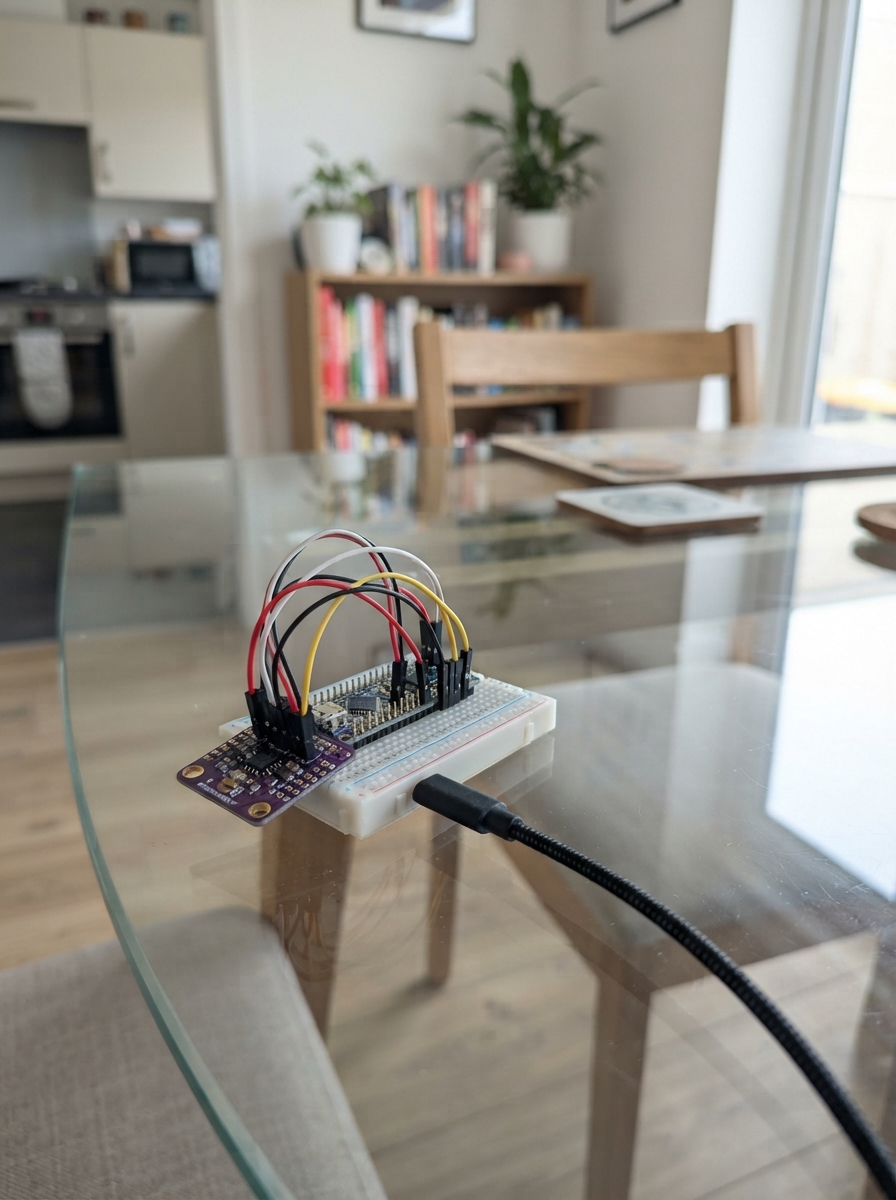
This project uses an Arduino Uno and MPU-6050 accelerometer to build a motion dashboard that captures and displays real-time acceleration data. The MPU-6050 sensor measures movement across three axes, providing the raw data needed to track device orientation and motion patterns.
The guide includes a complete wiring diagram showing how to connect the sensor to the Arduino via I2C pins, a full parts list, and ready-to-upload firmware that samples acceleration data at regular intervals and streams results to a serial monitor. Assembly takes just a few minutes: mount the sensor near the board, connect power and data lines, and start monitoring motion in real time.
Wiring diagram

Gather all the parts
Assemble it in 4 steps
1. ثبّت الحساس بجانب اللوحة
ضع Arduino Nano وحساس MPU-6050 على سطح غير موصل للكهرباء. اجعل وجه الحساس للأعلى، لأن اتجاهه هو الذي يحدد اتجاه حركة اللوحة الظاهرة في المتصفح.
- لا تحتاج إلى لحام إذا كان الحساس مزوداً برؤوس دبابيس وأسلاك توصيل.
- لا تضع اللوحة فوق معدن مكشوف؛ فقد يلامس المعدن الأرجل ويسبب قصرًا كهربائيًا.
2. صِل أسلاك الطاقة
صِل VIN في الحساس إلى 5V في Arduino Nano (power)، وصِل GND في الحساس إلى GND في Arduino Nano (ground).
- غالبًا يكون السلك الأحمر للطاقة والسلك الأسود للأرضي.
- تأكد أن VIN وGND غير متبادلين — توصيل الطاقة بالعكس قد يتلف الحساس.
3. صِل سلكَي القراءة
صِل SDA في الحساس إلى A4 في Arduino Nano، وهو GPIO18 (data)، وصِل SCL في الحساس إلى A5 في Arduino Nano، وهو GPIO19 (data). اترك طرف INT في الحساس غير موصول.
- ابحث عن الكلمات المطبوعة SDA وSCL على لوحة الحساس؛ لا تعتمد على ترتيب الأرجل فقط.
- لا توصل SDA أو SCL إلى 5V أو GND؛ هذه الأرجل تنقل القياسات وليست أسلاك طاقة.
4. ثبّت الحساس قبل التجربة
ثبّت الحساس على قطعة كرتون أو داخل علبة صغيرة، ثم صِل Arduino Nano بالحاسوب عبر USB. تثبيت الحساس يجعل الحركة التي تراها في المتصفح مطابقة للحركة التي تصنعها بيدك.
- إذا بدا الاتجاه معكوسًا، أدر الحساس 180 درجة أو عدّل اتجاهه المادي أولًا.
Review all connections
1. Connections between "mpu6050_1" and "Arduino"
Deploy the firmware
#include <Wire.h>

const uint8_t MPU6050_ADDRESS = 0x68;
const uint8_t MPU6050_POWER_REGISTER = 0x6B;
const uint8_t MPU6050_DATA_REGISTER = 0x3B;
const uint8_t I2C_SDA_PIN = A4;
const uint8_t I2C_SCL_PIN = A5;
const unsigned long SAMPLE_INTERVAL_MS = 50;

unsigned long lastSampleMs = 0;
float filteredPitch = 0.0f;
float filteredRoll = 0.0f;
bool filterReady = false;

bool writeRegister(uint8_t reg, uint8_t value) {
  Wire.beginTransmission(MPU6050_ADDRESS);
  Wire.write(reg);
  Wire.write(value);
  return Wire.endTransmission() == 0;
}

bool readAccelerometer(int16_t &ax, int16_t &ay, int16_t &az) {
  Wire.beginTransmission(MPU6050_ADDRESS);
  Wire.write(MPU6050_DATA_REGISTER);
  if (Wire.endTransmission(false) != 0) return false;

  const uint8_t wanted = 6;
  if (Wire.requestFrom(MPU6050_ADDRESS, wanted) != wanted) return false;

  ax = (int16_t)((Wire.read() << 8) | Wire.read());
  ay = (int16_t)((Wire.read() << 8) | Wire.read());
  az = (int16_t)((Wire.read() << 8) | Wire.read());
  return true;
}

void setup() {
  Serial.begin(115200);
  Wire.begin();
  delay(100);

  if (!writeRegister(MPU6050_POWER_REGISTER, 0x00)) {
    Serial.println(F("ERROR,MPU6050_NOT_FOUND"));
    while (true) delay(1000);
  }
  Serial.println(F("READY"));
}

void loop() {
  const unsigned long now = millis();
  if (now - lastSampleMs < SAMPLE_INTERVAL_MS) return;
  lastSampleMs = now;

  int16_t ax, ay, az;
  if (!readAccelerometer(ax, ay, az)) {
    Serial.println(F("ERROR,MPU6050_READ_FAILED"));
    return;
  }

  const float axf = (float)ax;
  const float ayf = (float)ay;
  const float azf = (float)az;
  const float pitch = atan2(ayf, sqrt(axf * axf + azf * azf)) * 180.0f / PI;
  const float roll = atan2(-axf, azf) * 180.0f / PI;

  if (!filterReady) {
    filteredPitch = pitch;
    filteredRoll = roll;
    filterReady = true;
  } else {
    const float smoothing = 0.22f;
    filteredPitch += smoothing * (pitch - filteredPitch);
    filteredRoll += smoothing * (roll - filteredRoll);
  }

  Serial.print(filteredPitch, 1);
  Serial.print(',');
  Serial.println(filteredRoll, 1);
}
Remix this project
Make it yours in one click
Open a full copy of this project in your own Schematik workspace — diagram, code, parts, and assembly steps included. Swap the sensor, add features, or redesign the whole thing with AI. The author's original stays untouched.