Community project
Automatic Pet Watering
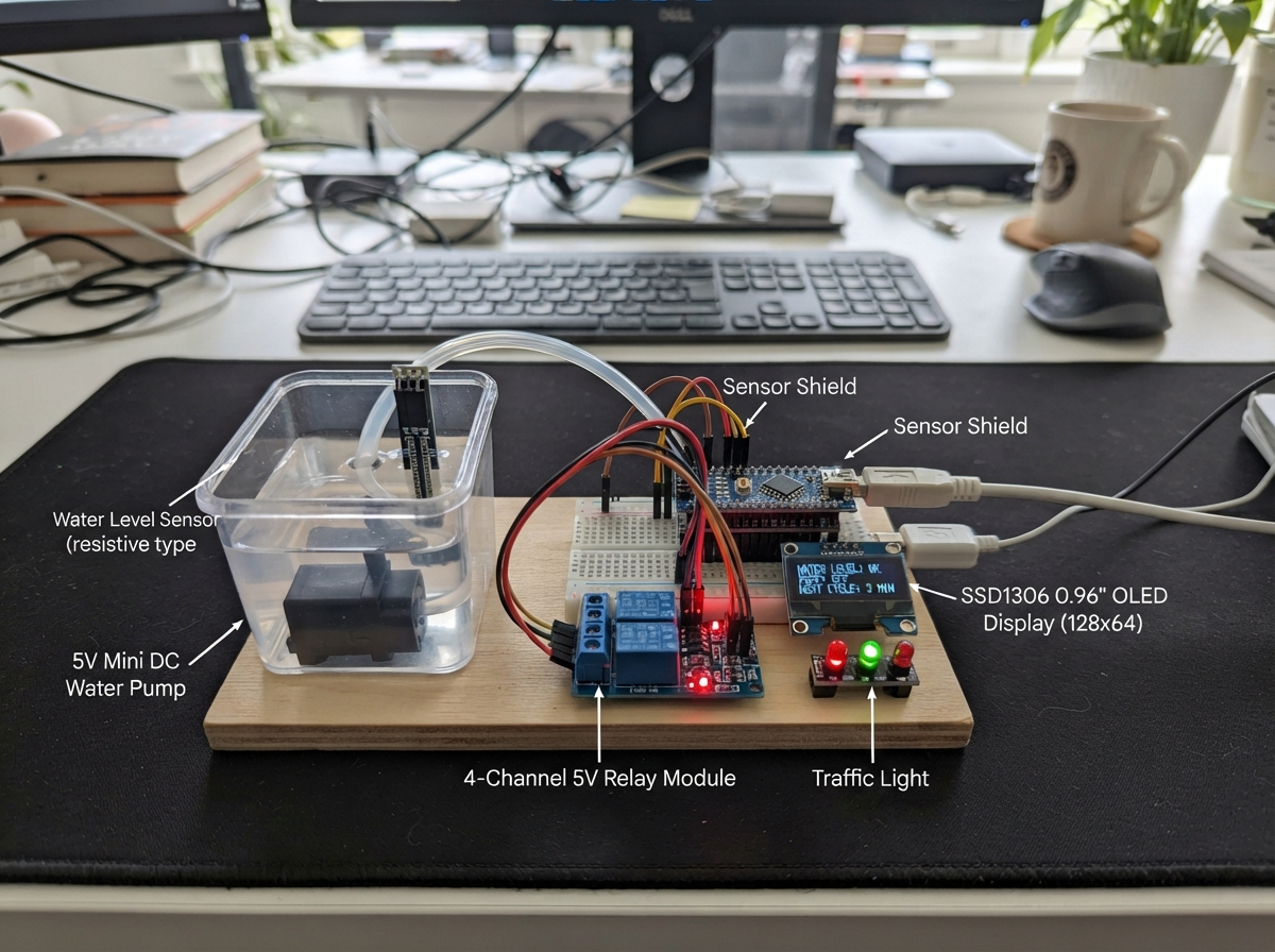
This automatic pet watering system monitors a water bowl and activates a pump when the level drops too low, ensuring pets always have access to fresh water. Built around an Arduino Uno with a water level sensor, relay-controlled pump, OLED display, and traffic light indicators, the system provides visual feedback on water status and pump operation.
The guide includes a complete wiring diagram, parts list with supplier links, Arduino firmware with hysteresis-based water detection, and step-by-step assembly instructions. Builders will learn how to integrate analog sensors, control high-current devices through relays, and create a responsive user interface with display and LED indicators.
Wiring diagram

Gather all the parts
Assemble it in 7 steps
1. Fit the Nano into the sensor shield
With all power disconnected, press the Arduino Nano straight into the two socket rows on the Arduino Nano Sensor Shield. Match the printed labels and make sure no Nano pin is bent. The shield’s S, V, and G header holes provide the Nano’s signal, 5 V, and ground connections.
- Do not connect the wall adapter while moving wires; a loose powered wire can damage the boards.
2. Connect the wall adapter to the power module
Connect the wall adapter positive output to the DC-DC multi-output module VIN+ input (power), and the adapter negative output to VIN− (ground). Set and check the module’s logic output at 5.0 V before connecting the Nano.
- Never connect the 12 V adapter output to the 5 V logic terminals; that can damage the Nano, OLED, relay board, and sensor.
3. Make the 5 V logic rail
Connect the power module 5V LOGIC+ output to the Nano Sensor Shield 5V rail (power). Connect the power module LOGIC GND to the Sensor Shield GND rail (ground). This rail powers the Nano and the low-power modules.
- Use red wire for 5 V and black wire for ground so the connections are easier to inspect.
4. Connect the water sensor, screen, and lights
Water sensor: + → shield 5V (power), − → shield GND (ground), S → A0-S (water-level signal). OLED: VCC → shield 5V (power), GND → shield GND (ground), SDA → A4-S (data), SCL → A5-S (clock). Traffic-light module: GND → shield GND (ground), RED → D3-S (low-water light), YELLOW → D4-S (status light), GREEN → D5-S (water-level-OK light).
- Keep the display and shield dry; only the sensing end of the water sensor belongs near the water.
- Make sure the traffic-light module has built-in LED resistors. Bare LEDs without resistors can damage the LEDs or the Nano pins.
5. Connect relay channel 1 and the pump circuit
Relay control side: VCC → shield 5V (power), GND → shield GND (ground), IN1 → D2-S (pump-control signal). Pump circuit: power module 5V PUMP+ → relay COM1 (power entering the switch), relay NO1 → pump PUMP+ (switched pump power), pump PUMP− → power module PUMP GND (ground return). Leave NC1, IN2, IN3, and IN4 unconnected.
- This wiring is for the listed 5 V pump. Use a pump-output rail matching the pump label if you replace the pump with another voltage.
- Keep the pump leads away from the OLED and water-sensor signal wires, and tighten the relay screw terminals.
6. Check the supply before wet testing
Verify that the logic output measures 5 V and that the pump output is set to the voltage printed on the pump. Confirm that COM1 and NO1 are the screw terminals printed for relay channel 1; do not rely on their left-to-right position. Keep the pump inlet submerged before allowing it to run.
- If the Nano resets, the screen flickers, or the supply gets very hot when the pump starts, disconnect power. The power module needs a pump output with enough current capacity.
7. Connect the programming cable
Connect the programming cable between the computer and the Nano’s USB programming connector. It is only for programming and serial messages; the DC-DC power module supplies the circuit during use.
- A standard Nano normally uses Mini-USB, not full-size USB-B. Check that your cable physically fits; do not force the connector.
Review all connections
1. Connections between "adapter_1" and "Arduino"
2. Connections between "power_module_1" and "Arduino"
3. Connections between "water_sensor_1" and "Arduino"
4. Connections between "relay_4ch_1" and "Arduino"
5. Connections between "pump_1" and "Arduino"
6. Connections between "traffic_light_1" and "Arduino"
7. Connections between "oled_1" and "Arduino"
8. Connections between "usb_cable_1" and "Arduino"
Deploy the firmware
#include <Wire.h>
#include <Adafruit_GFX.h>
#include <Adafruit_SSD1306.h>

const uint8_t WATER_SENSOR_PIN = A0;
const uint8_t RELAY_PIN = 2;
const uint8_t LED_RED_PIN = 3;
const uint8_t LED_YELLOW_PIN = 4;
const uint8_t LED_GREEN_PIN = 5;

const uint8_t SCREEN_WIDTH = 128;
const uint8_t SCREEN_HEIGHT = 64;
const int LOW_WATER_THRESHOLD = 300;
const int HYSTERESIS = 30;
const unsigned long SAMPLE_INTERVAL_MS = 500;

Adafruit_SSD1306 display(SCREEN_WIDTH, SCREEN_HEIGHT, &Wire, -1);

bool pumpOn = false;
int waterReading = -1;
int shownReading = -1;
bool shownPumpState = false;
unsigned long lastSampleMs = 0;

void setPump(bool on) {
  pumpOn = on;
  // Most 4-channel relay boards are active-low: LOW energizes relay channel 1.
  digitalWrite(RELAY_PIN, on ? LOW : HIGH);

  digitalWrite(LED_RED_PIN, on ? HIGH : LOW);
  digitalWrite(LED_YELLOW_PIN, LOW);
  digitalWrite(LED_GREEN_PIN, on ? LOW : HIGH);
}

void drawStatus(bool force) {
  if (!force && waterReading == shownReading && pumpOn == shownPumpState) {
    return;
  }

  display.clearDisplay();
  display.setTextColor(SSD1306_WHITE);
  display.setTextSize(1);
  display.setCursor(0, 0);
  display.println(F("PET WATER DISPENSER"));
  display.drawLine(0, 11, 127, 11, SSD1306_WHITE);
  display.setCursor(0, 18);
  display.print(F("Water reading: "));
  display.println(waterReading);
  display.setCursor(0, 34);
  display.print(F("Level: "));
  display.println(waterReading < LOW_WATER_THRESHOLD ? F("LOW") : F("OK"));
  display.setCursor(0, 50);
  display.print(F("Pump: "));
  display.println(pumpOn ? F("FILLING") : F("OFF"));
  display.display();

  shownReading = waterReading;
  shownPumpState = pumpOn;
}

void setup() {
  pinMode(RELAY_PIN, OUTPUT);
  pinMode(LED_RED_PIN, OUTPUT);
  pinMode(LED_YELLOW_PIN, OUTPUT);
  pinMode(LED_GREEN_PIN, OUTPUT);
  setPump(false);

  Serial.begin(9600);
  Wire.begin();
  if (!display.begin(SSD1306_SWITCHCAPVCC, 0x3C)) {
    Serial.println(F("OLED not found at 0x3C"));
  } else {
    drawStatus(true);
  }
}

void loop() {
  const unsigned long now = millis();
  if (now - lastSampleMs < SAMPLE_INTERVAL_MS) {
    return;
  }
  lastSampleMs = now;

  waterReading = analogRead(WATER_SENSOR_PIN);
  if (!pumpOn && waterReading < LOW_WATER_THRESHOLD) {
    setPump(true);
  } else if (pumpOn && waterReading >= LOW_WATER_THRESHOLD + HYSTERESIS) {
    setPump(false);
  }

  Serial.print(F("Water reading: "));
  Serial.print(waterReading);
  Serial.print(F(", pump: "));
  Serial.println(pumpOn ? F("ON") : F("OFF"));
  drawStatus(false);
}
Remix this project
Make it yours in one click
Open a full copy of this project in your own Schematik workspace — diagram, code, parts, and assembly steps included. Swap the sensor, add features, or redesign the whole thing with AI. The author's original stays untouched.