Community project
Multi-Channel Battery Monitor
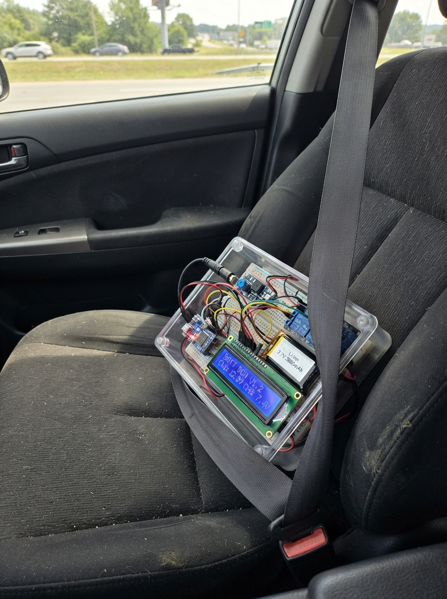
This project builds a smart charging system that monitors and manages up to three lithium-ion batteries simultaneously. Using an Arduino Uno, relay modules, and TP4056 charger boards, the system automatically cycles through charging phases while measuring voltage across each battery and displaying real-time status on a 16x2 LCD screen.
The guide provides a complete wiring diagram, parts list, and step-by-step assembly instructions to connect the barrel jack power input, buck converter, relay-controlled chargers, voltage divider networks, and I2C LCD display. The included firmware handles charge cycle timing, voltage sampling, battery detection, and multi-page display output to track charging progress and battery health.
Wiring diagram

Gather all the parts
Assemble it in 8 steps
1. Turn off the power first
Unplug the 12 V adapter and unplug the Uno USB cable before moving any wire. This prevents a loose wire from touching the wrong place while you work.
- Do not connect a lithium cell backwards; reversed battery wires can damage the TP4056 board or the cell.
2. Set the 5 V converter
Connect the 12 V adapter to the buck converter VIN+ and VIN−. Use a multimeter to adjust its output to exactly 5.00 V before connecting the Uno, relay boards, LCD, or TP4056 boards.
- An output above 5 V can damage the Uno, LCD, relay boards, and TP4056 charger boards.
3. Make one common ground
Join buck converter VOUT− to Uno GND, both relay-board GND pins, all three TP4056 IN− pins, all three TP4056 OUT− pins, and the LCD GND. These black or negative wires give the Arduino voltage readings a correct reference.
- Keep the ground wires short and secure.
4. Wire the charger power relays
Connect buck VOUT+ to the Uno 5V pin (power), both relay-board VCC pins (power), LCD VCC (power), and the relay COM terminals (charger power). Connect relay board 1 NO1 to charger 1 IN+ (charger 1 power), relay board 1 NO2 to charger 2 IN+ (charger 2 power), and relay board 2 NO1 to charger 3 IN+ (charger 3 power). Connect relay board 1 IN1 to Uno D2 (control), IN2 to D3 (control), and relay board 2 IN1 to D4 (control).
- Use the NO terminal, not NC, so a charger loses power when the Uno is off.
- Leave the unused IN2, COM2, and NO2 terminals on relay board 2 disconnected.
5. Connect each battery to its own charger
Connect Battery 1 positive to charger 1 B+ (battery power) and negative to B− (battery ground). Repeat for Battery 2 with charger 2 and Battery 3 with charger 3. Do not join the three batteries together.
- Do not use a cell that reads about 1.2 V. A normal single lithium-ion cell is normally about 3.0 V to 4.2 V; a 1.2 V reading can mean the cell is damaged or is not the correct battery type.
6. Wire the three safe voltage measurements
For each charger, connect one 10 kΩ resistor from B+ to a junction. Connect the other 10 kΩ resistor from that same junction to GND. Connect charger 1’s junction to Uno A0 (voltage reading), charger 2’s junction to A1 (voltage reading), and charger 3’s junction to A2 (voltage reading). Do not connect B+ directly to an Arduino pin.
- B+ measures the cell itself. OUT+ can be disconnected by the TP4056 protection circuit and can give a misleading low-battery reading.
7. Connect the 16 by 2 LCD display
Connect LCD VCC to regulated 5 V (power), LCD GND to common GND (ground), LCD SDA to Uno A4 (data), and LCD SCL to Uno A5 (clock).
- Make sure VCC and GND are not swapped — swapped power can damage the display.
8. Power and check the display cycle
Check every connection once more, then connect the Uno by USB and the 12 V adapter. The LCD shows voltage for 30 seconds, estimated percentage for 30 seconds, then charging state for 30 seconds. It charges for two minutes, turns all three relays off for three seconds while it averages A0, A1, and A2, then starts the next two-minute charge period.
- Compare each displayed voltage with a multimeter between the same TP4056 B+ and B− terminals.
- A channel becomes FULL at 4.20 V, or after eight minutes without at least a 0.01 V rise across successive two-minute checks.
Review all connections
1. Connections between "supply_12v" and "Arduino"
2. Connections between "buck_5v" and "Arduino"
3. Connections between "charger_1" and "Arduino"
4. Connections between "charger_2" and "Arduino"
5. Connections between "charger_3" and "Arduino"
6. Connections between "divider_1_top" and "Arduino"
7. Connections between "divider_1_bottom" and "Arduino"
8. Connections between "divider_2_top" and "Arduino"
9. Connections between "divider_2_bottom" and "Arduino"
10. Connections between "divider_3_top" and "Arduino"
11. Connections between "divider_3_bottom" and "Arduino"
12. Connections between "lcd_1" and "Arduino"
13. Connections between "relay_board_1" and "Arduino"
14. Connections between "relay_board_2" and "Arduino"
Deploy the firmware
#include <Arduino.h>
#include <Wire.h>
#include <LiquidCrystal_I2C.h>
#include <stdio.h>

const uint8_t RELAY_1_PIN = 2;
const uint8_t RELAY_2_PIN = 3;
const uint8_t RELAY_3_PIN = 4;
const uint8_t BATTERY_1_PIN = A0;
const uint8_t BATTERY_2_PIN = A1;
const uint8_t BATTERY_3_PIN = A2;

// Measure the Uno 5 V pin with a multimeter and adjust this value if needed.
const float ADC_REFERENCE_VOLTS = 5.00f;
const float DIVIDER_RATIO = 2.0f;       // two equal 10 kΩ resistors
const float FULL_VOLTAGE = 4.20f;
const float DISCONNECTED_VOLTAGE = 0.20f;
const float MEANINGFUL_RISE_VOLTS = 0.01f;
const unsigned long CHARGE_TIME_MS = 120000UL;
const unsigned long REST_AND_SAMPLE_TIME_MS = 3000UL;
const unsigned long NO_RISE_FULL_TIME_MS = 480000UL;
const unsigned long SAMPLE_GAP_MS = 100UL;
const unsigned long DISPLAY_UPDATE_MS = 500UL;
const unsigned long PAGE_TIME_MS = 30000UL;

// Most 5 V relay boards are active LOW. Reverse these two values only if your
// particular board turns a relay on when its IN pin is HIGH.
const uint8_t RELAY_ON = LOW;
const uint8_t RELAY_OFF = HIGH;

// Standard 16x2 I2C backpack address for the selected LCD.
LiquidCrystal_I2C lcd(0x27, 16, 2);
const uint8_t relayPins[3] = {RELAY_1_PIN, RELAY_2_PIN, RELAY_3_PIN};
const uint8_t batteryPins[3] = {BATTERY_1_PIN, BATTERY_2_PIN, BATTERY_3_PIN};

enum CyclePhase { CHARGING, RESTING_AND_SAMPLING };
enum DisplayPage { VOLTAGE_PAGE, PERCENT_PAGE, STATUS_PAGE };
CyclePhase phase = CHARGING;
DisplayPage displayPage = VOLTAGE_PAGE;
bool chargeComplete[3] = {false, false, false};
bool batteryMissing[3] = {false, false, false};
bool haveBaseline[3] = {false, false, false};
float batteryVolts[3] = {0.0f, 0.0f, 0.0f};
float lastRisingVoltage[3] = {0.0f, 0.0f, 0.0f};
float sampleSum[3] = {0.0f, 0.0f, 0.0f};
uint16_t sampleCount = 0;
unsigned long phaseStartedMs = 0;
unsigned long pageStartedMs = 0;
unsigned long lastSampleMs = 0;
unsigned long lastRiseMs[3] = {0UL, 0UL, 0UL};
unsigned long lastDisplayMs = 0;

float readBatteryVoltage(uint8_t analogPin) {
  analogRead(analogPin); // discard the first reading after changing channels
  unsigned long total = 0;
  for (uint8_t i = 0; i < 8; ++i) total += analogRead(analogPin);
  return ((total / 8.0f) * ADC_REFERENCE_VOLTS / 1023.0f) * DIVIDER_RATIO;
}

void setRelay(uint8_t channel, bool enableCharging) {
  digitalWrite(relayPins[channel], enableCharging ? RELAY_ON : RELAY_OFF);
}

uint8_t batteryPercent(float volts) {
  if (volts < 3.00f) return 0;
  if (volts >= FULL_VOLTAGE) return 100;
  if (volts >= 4.10f) return (uint8_t)(90.0f + (volts - 4.10f) * 100.0f);
  if (volts >= 4.00f) return (uint8_t)(75.0f + (volts - 4.00f) * 150.0f);
  if (volts >= 3.90f) return (uint8_t)(55.0f + (volts - 3.90f) * 200.0f);
  if (volts >= 3.80f) return (uint8_t)(35.0f + (volts - 3.80f) * 200.0f);
  if (volts >= 3.70f) return (uint8_t)(15.0f + (volts - 3.70f) * 200.0f);
  if (volts >= 3.50f) return (uint8_t)((volts - 3.50f) * 75.0f);
  return 0;
}

void writeLine(uint8_t row, const char *text) {
  lcd.setCursor(0, row);
  lcd.print(text);
  for (uint8_t i = strlen(text); i < 16; ++i) lcd.print(' ');
}

const char *statusText(uint8_t channel) {
  if (batteryMissing[channel]) return "NULL";
  if (chargeComplete[channel]) return "FULL";
  return "CHG";
}

void drawDisplay() {
  char line[17];
  if (displayPage == VOLTAGE_PAGE) {
    if (batteryMissing[0] && batteryMissing[1]) {
      snprintf(line, sizeof(line), "B1:NULL B2:NULL");
    } else if (batteryMissing[0]) {
      snprintf(line, sizeof(line), "B1:NULL B2:%.2f", batteryVolts[1]);
    } else if (batteryMissing[1]) {
      snprintf(line, sizeof(line), "B1:%.2f B2:NULL", batteryVolts[0]);
    } else {
      snprintf(line, sizeof(line), "B1:%.2f B2:%.2f", batteryVolts[0], batteryVolts[1]);
    }
    writeLine(0, line);
    if (batteryMissing[2]) snprintf(line, sizeof(line), "B3:NULL");
    else snprintf(line, sizeof(line), "B3:%.2fV", batteryVolts[2]);
    writeLine(1, line);
  } else if (displayPage == PERCENT_PAGE) {
    snprintf(line, sizeof(line), "B1:%3u%% B2:%3u%%",
             batteryMissing[0] ? 0 : batteryPercent(batteryVolts[0]),
             batteryMissing[1] ? 0 : batteryPercent(batteryVolts[1]));
    writeLine(0, line);
    if (batteryMissing[2]) snprintf(line, sizeof(line), "B3:NULL");
    else snprintf(line, sizeof(line), "B3:%3u%%", batteryPercent(batteryVolts[2]));
    writeLine(1, line);
  } else {
    snprintf(line, sizeof(line), "B1:%s B2:%s", statusText(0), statusText(1));
    writeLine(0, line);
    snprintf(line, sizeof(line), "B3:%s", statusText(2));
    writeLine(1, line);
  }
}

void beginRestAndSampling(unsigned long now) {
  phase = RESTING_AND_SAMPLING;
  phaseStartedMs = now;
  lastSampleMs = 0;
  sampleCount = 0;
  for (uint8_t channel = 0; channel < 3; ++channel) {
    sampleSum[channel] = 0.0f;
    setRelay(channel, false); // all chargers are off for the 3-second reading
  }
}

void finishSampling(unsigned long now) {
  if (sampleCount > 0) {
    for (uint8_t channel = 0; channel < 3; ++channel) {
      batteryVolts[channel] = sampleSum[channel] / sampleCount;
      batteryMissing[channel] = batteryVolts[channel] < DISCONNECTED_VOLTAGE;

      if (batteryMissing[channel]) {
        chargeComplete[channel] = false;
        haveBaseline[channel] = false;
      } else if (batteryVolts[channel] >= FULL_VOLTAGE) {
        chargeComplete[channel] = true;
      } else if (!haveBaseline[channel]) {
        haveBaseline[channel] = true;
        lastRisingVoltage[channel] = batteryVolts[channel];
        lastRiseMs[channel] = now;
      } else if (batteryVolts[channel] >= lastRisingVoltage[channel] + MEANINGFUL_RISE_VOLTS) {
        lastRisingVoltage[channel] = batteryVolts[channel];
        lastRiseMs[channel] = now;
      } else if (now - lastRiseMs[channel] >= NO_RISE_FULL_TIME_MS) {
        // Eight minutes without a 10 mV rise means this channel is treated as full.
        chargeComplete[channel] = true;
      }
    }
  }

  phase = CHARGING;
  phaseStartedMs = now;
  for (uint8_t channel = 0; channel < 3; ++channel) {
    setRelay(channel, !batteryMissing[channel] && !chargeComplete[channel]);
  }
}

void setup() {
  for (uint8_t channel = 0; channel < 3; ++channel) {
    pinMode(relayPins[channel], OUTPUT);
    setRelay(channel, true);
  }
  Wire.begin();
  lcd.init();
  lcd.backlight();
  lcd.clear();
  phaseStartedMs = millis();
  pageStartedMs = phaseStartedMs;
}

void loop() {
  const unsigned long now = millis();

  if (phase == CHARGING && now - phaseStartedMs >= CHARGE_TIME_MS) {
    beginRestAndSampling(now);
  }

  if (phase == RESTING_AND_SAMPLING) {
    if (now - lastSampleMs >= SAMPLE_GAP_MS) {
      lastSampleMs = now;
      for (uint8_t channel = 0; channel < 3; ++channel) {
        sampleSum[channel] += readBatteryVoltage(batteryPins[channel]);
      }
      ++sampleCount;
    }
    if (now - phaseStartedMs >= REST_AND_SAMPLE_TIME_MS) {
      finishSampling(now);
    }
  }

  if (now - pageStartedMs >= PAGE_TIME_MS) {
    pageStartedMs = now;
    displayPage = (DisplayPage)((displayPage + 1) % 3);
    lcd.clear();
  }

  if (now - lastDisplayMs >= DISPLAY_UPDATE_MS) {
    lastDisplayMs = now;
    drawDisplay();
  }
}
Remix this project
Make it yours in one click
Open a full copy of this project in your own Schematik workspace — diagram, code, parts, and assembly steps included. Swap the sensor, add features, or redesign the whole thing with AI. The author's original stays untouched.