Community project
Arduino Fan Controller
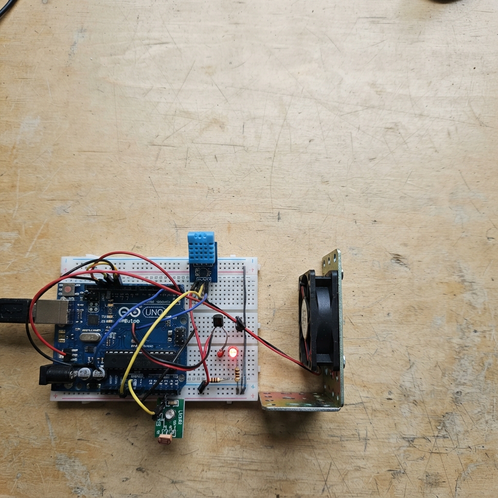
This Arduino Uno project creates a fan controller with environmental monitoring. The fan and indicator LED switch on and off in 5-second intervals, while a DHT11 temperature/humidity sensor and LM393 light sensor continuously monitor conditions and report readings to the Serial console. The fan is driven through an NPN transistor circuit with a protective diode, allowing the Arduino's digital pin to safely control the 5 V DC motor.
The guide provides a complete wiring diagram showing how to connect the transistor, diode, sensors, and fan to the Arduino, along with a full parts list and step-by-step assembly instructions. Upload the provided firmware to get started, then open the Serial monitor to watch real-time temperature, humidity, and light level data while the fan cycles automatically.
Wiring diagram

Gather all the parts
Assemble it in 6 steps
1. Place the Arduino and keep USB unplugged
Put the Arduino Uno beside the breadboard. Leave its USB cable unplugged while you make the wires, so a wrong connection cannot power the circuit.
- Do not power the Arduino until you have checked the fan diode and all 5V and GND wires.
2. Keep the fan switch wiring
Keep the fan circuit already built: Arduino D9 goes through the 220 Ω base resistor to the 2N2222 base (control signal). The emitter goes to GND (ground), and the collector goes to the fan negative lead. Connect the fan positive lead to 5V (power). Put the 1N4007 across the fan: striped end to 5V and unstriped end to the fan negative/collector point (protects the transistor when the fan stops).
- Check the 2N2222 package marking for its actual base, collector, and emitter leg order before inserting it.
- The striped diode end must go to 5V; reversing it creates a short circuit when the fan is switched on.
3. Keep the indicator LED wiring
Keep Arduino D8 connected through its 220 Ω resistor to the LED long leg or positive input (light control). Connect the LED short leg or negative input to GND (ground).
- Do not connect the LED directly to an Arduino pin without its 220 Ω resistor; too much current can damage the LED or Arduino pin.
4. Wire the DHT11 sensor
Connect DHT11 VCC to Arduino 3.3V (power), GND to Arduino GND (ground), and DATA to Arduino D2 (signal).
- Most three-pin DHT11 modules already include the small pull-up resistor, so they only need VCC, GND, and DATA.
- Make sure VCC and GND are not swapped — swapped power can damage the sensor.
5. Wire the light sensor module from the photo
Use the four-pin side labelled VCC, GND, DO, and AO. Connect VCC to Arduino 5V (power), GND to Arduino GND (ground), and AO to Arduino A0 (brightness signal). Leave DO unconnected; the program reads AO so it can show the full changing light level rather than only dark or bright.
- The small blue screw adjusts when DO changes state, but it does not affect the AO connection used by this program.
- The LDR is already fitted on this board, so do not add the old loose LDR or 10 kΩ resistor.
6. Check shared power and upload
Make sure every GND wire joins an Arduino GND pin. Recheck that D2 is only the DHT11 DATA wire and A0 is only the light module AO wire. Then plug the Uno into USB.
- After deploying, open the Serial Monitor at 9600 baud to see light, temperature, and humidity readings every two seconds.
Review all connections
1. Connections between "fan_5v" and "Arduino"
2. Connections between "transistor_2n2222" and "Arduino"
3. Connections between "base_resistor_1k" and "Arduino"
4. Connections between "flyback_1n4007" and "Arduino"
5. Connections between "led_resistor_220" and "Arduino"
6. Connections between "indicator_led" and "Arduino"
7. Connections between "dht11_1" and "Arduino"
8. Connections between "light_sensor_lm393" and "Arduino"
Deploy the firmware
// Arduino Uno fan switch with an indicator LED, DHT11, and LM393 light sensor module.
// The fan and LED switch on for 5 seconds, then off for 5 seconds.
// Temperature, humidity, and light are read independently and printed to Serial.

#include <Arduino.h>
#include <DHT.h>

const uint8_t FAN_CONTROL_PIN = 9;
const uint8_t LED_PIN = 8;
const uint8_t DHT_PIN = 2;
const uint8_t LDR_PIN = A0;

const unsigned long SWITCH_INTERVAL_MS = 5000;
const unsigned long SENSOR_INTERVAL_MS = 2000;

DHT dht(DHT_PIN, DHT11);

bool outputOn = false;
unsigned long lastSwitchMs = 0;
unsigned long lastSensorMs = 0;

void setOutputs(bool turnOn) {
  digitalWrite(FAN_CONTROL_PIN, turnOn ? HIGH : LOW);
  digitalWrite(LED_PIN, turnOn ? HIGH : LOW);
}

void printSensorReadings() {
  float humidity = dht.readHumidity();
  float temperatureC = dht.readTemperature();
  int lightLevel = analogRead(LDR_PIN);

  Serial.print("Light sensor value (0-1023): ");
  Serial.println(lightLevel);

  if (isnan(humidity) || isnan(temperatureC)) {
    Serial.println("DHT11 reading failed. Check its power, ground, and DATA wire.");
    return;
  }

  Serial.print("Temperature: ");
  Serial.print(temperatureC, 1);
  Serial.println(" C");
  Serial.print("Humidity: ");
  Serial.print(humidity, 0);
  Serial.println(" %");
}

void setup() {
  pinMode(FAN_CONTROL_PIN, OUTPUT);
  pinMode(LED_PIN, OUTPUT);
  setOutputs(false);

  Serial.begin(9600);
  dht.begin();

  lastSwitchMs = millis();
  lastSensorMs = millis() - SENSOR_INTERVAL_MS;
}

void loop() {
  unsigned long now = millis();

  if (now - lastSwitchMs >= SWITCH_INTERVAL_MS) {
    lastSwitchMs = now;
    outputOn = !outputOn;
    setOutputs(outputOn);
  }

  if (now - lastSensorMs >= SENSOR_INTERVAL_MS) {
    lastSensorMs = now;
    printSensorReadings();
  }
}
Remix this project
Make it yours in one click
Open a full copy of this project in your own Schematik workspace — diagram, code, parts, and assembly steps included. Swap the sensor, add features, or redesign the whole thing with AI. The author's original stays untouched.