Community project
Acoustic Drone Detection
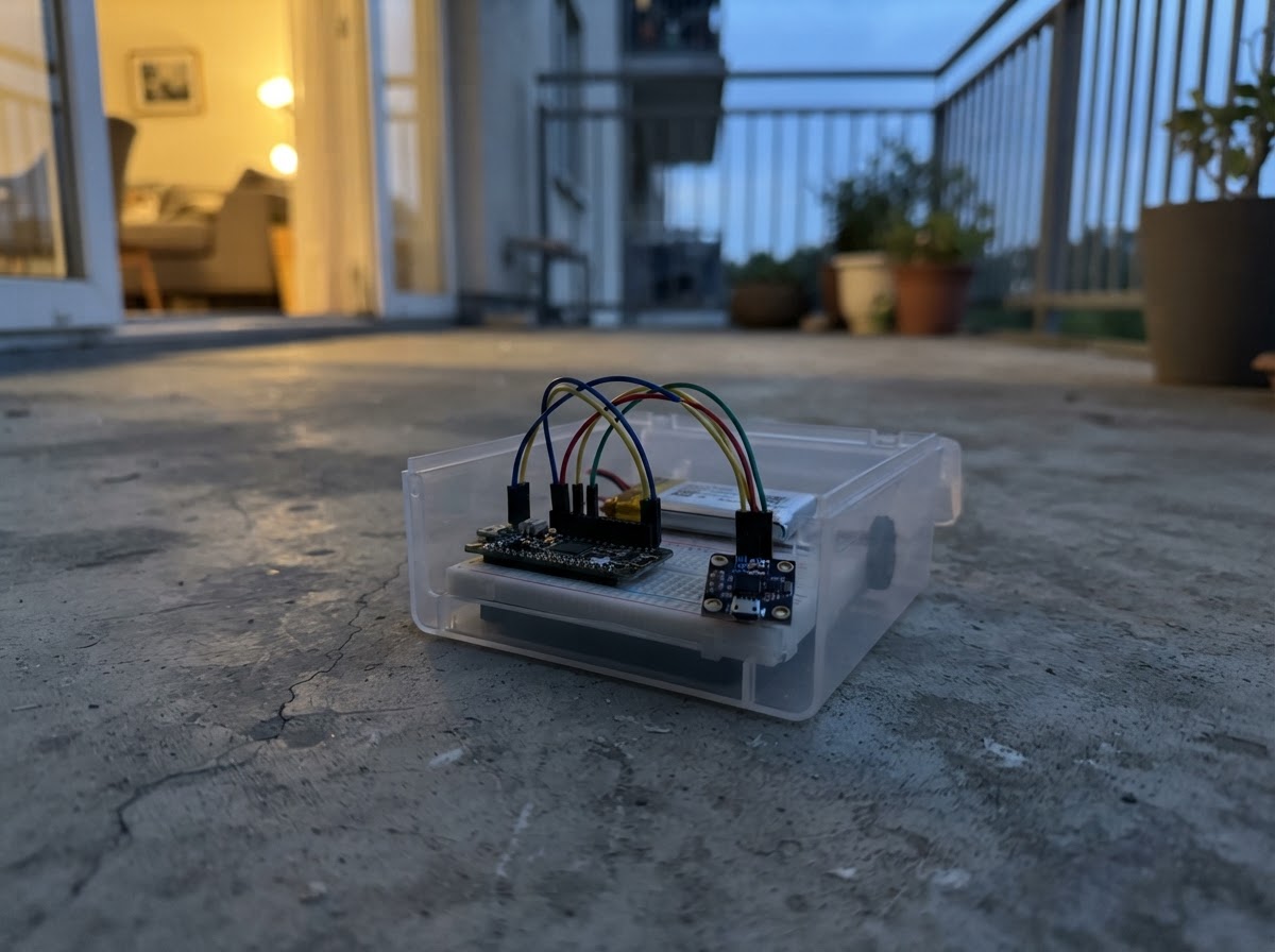
This project uses four INMP441 microphones connected to an ESP32 to detect and stream acoustic signatures of drones. The microphones are arranged in two stereo pairs, each fed into a separate I²S interface on the ESP32, allowing simultaneous capture of audio from multiple directions.
The guide provides a complete wiring diagram showing how to connect all four microphones to the ESP32, a full parts list, and Arduino firmware that broadcasts the audio streams over WiFi to a connected laptop. Assembly involves mounting the board and microphones, powering each microphone safely, wiring the two stereo pairs, and configuring your laptop to receive and analyze the audio data.
Wiring diagram

Gather all the parts
Assemble it in 5 steps
1. Place the board and microphones
Put the ESP32 DevKit v1 on a non-metal surface with the USB-C connector on the right, as in your photo. The writing on the board calls the pins D25, D26, D32, and so on; those are the same pins the diagram calls GPIO25, GPIO26, GPIO32. Place the four microphone boards in a square and label them 1 through 4. Keep each tiny microphone opening uncovered and away from the board’s metal Wi-Fi antenna end.
- Keeping the microphone positions fixed and labelled makes it easier for your laptop software to identify each recording channel.
- Do not let loose wires or microphone boards touch metal while USB power is connected; a short circuit can damage the board.
2. Give every microphone safe power
Connect each microphone VDD pin to the board pin printed 3V3 (power), and each microphone GND pin to either board pin printed GND (ground). The four boards may share breadboard power rows.
- Use red wires for 3V3 and black wires for GND so the power wiring is easy to inspect.
- Do not connect a microphone VDD pin to 5V or VIN — these microphones use 3.3V and 5V can damage them.
3. Wire microphones 1 and 2
Use the labels printed on your board: microphone 1 SCK → D25 / GPIO25 (clock), WS → D26 / GPIO26 (left-right timing), and SD → D32 / GPIO32 (audio signal). Microphone 2 SCK → microphone 1 SCK (clock), WS → microphone 1 WS (left-right timing), and SD → microphone 1 SD (audio signal). Microphone 1 L/R → GND (selects the left channel); microphone 2 L/R → 3V3 (selects the right channel).
- The two SD pins join on purpose: the L/R wires make the microphones take turns on the shared audio signal wire.
- Make sure microphone 1 L/R is connected to GND and microphone 2 L/R is connected to 3V3. If both are connected the same way, one channel will be missing or duplicated.
4. Wire microphones 3 and 4
Use the labels printed on your board: microphone 3 SCK → D27 / GPIO27 (clock), WS → D14 / GPIO14 (left-right timing), and SD → D33 / GPIO33 (audio signal). Microphone 4 SCK → microphone 3 SCK (clock), WS → microphone 3 WS (left-right timing), and SD → microphone 3 SD (audio signal). Microphone 3 L/R → GND (selects the left channel); microphone 4 L/R → 3V3 (selects the right channel).
- Keep each group of clock and audio wires short and together to help avoid noise in the recordings.
- Do not join the SD wire for microphones 1–2 to the SD wire for microphones 3–4; the two microphone pairs need separate audio signal wires.
5. Connect the laptop and stream audio
Plug the ESP32 DevKit into USB for power. On the Linux laptop, join the Wi-Fi network named DroneAudio-ESP32 using password droneaudio. Listen for UDP packets on port 3333: stream 0 contains microphones 1 and 2, and stream 1 contains microphones 3 and 4. Each packet begins with DAUD, followed by a 16-byte header and 64 stereo frames of signed 16-bit PCM audio.
- The laptop receives two independent 16 kHz stereo streams: samples alternate left then right within each stream.
- While connected to the ESP32 Wi-Fi network, the laptop may not have Internet access because this network is dedicated to the audio link.
Review all connections
1. Connections between "mic_1" and "ESP32"
2. Connections between "mic_2" and "ESP32"
3. Connections between "mic_3" and "ESP32"
4. Connections between "mic_4" and "ESP32"
Deploy the firmware
#include <Arduino.h>
#include <WiFi.h>
#include <WiFiUdp.h>
#include "driver/i2s.h"

// The laptop joins this Wi-Fi network. Audio is broadcast to UDP port 3333,
// so the receiver can listen on any address assigned by this access point.
struct __attribute__((packed)) AudioPacketHeader {
  char magic[4];       // Always "DAUD".
  uint8_t version;     // Packet format version: 1.
  uint8_t streamId;    // 0 = microphones 1/2, 1 = microphones 3/4.
  uint16_t sequence;   // Increases by one for each packet in a stream.
  uint32_t sampleRate; // Samples per channel per second: 16000.
  uint16_t channels;   // Always 2: left, right, left, right.
  uint16_t frames;     // Frames in this packet: 64.
};


// Forward declarations
static void configureI2s(i2s_port_t port, int bclk, int ws, int dataIn);
static bool readAndSend(i2s_port_t port, uint8_t streamId, uint16_t &sequence);

static const char *AP_NAME = "DroneAudio-ESP32";
static const char *AP_PASSWORD = "droneaudio";
static const uint16_t UDP_PORT = 3333;
static const IPAddress UDP_BROADCAST(192, 168, 4, 255);

static const int SAMPLE_RATE_HZ = 16000;
static const size_t FRAMES_PER_PACKET = 64;
static const size_t STEREO_WORDS = FRAMES_PER_PACKET * 2;

// Pair A: microphones 1 (left) and 2 (right), I2S0.
static const int PAIR_A_BCLK = 25;
static const int PAIR_A_WS = 26;
static const int PAIR_A_DATA = 32;
// Pair B: microphones 3 (left) and 4 (right), I2S1.
static const int PAIR_B_BCLK = 27;
static const int PAIR_B_WS = 14;
static const int PAIR_B_DATA = 33;

WiFiUDP udp;
uint16_t sequenceA = 0;
uint16_t sequenceB = 0;

static void configureI2s(i2s_port_t port, int bclk, int ws, int dataIn) {
  i2s_config_t config = {};
  config.mode = (i2s_mode_t)(I2S_MODE_MASTER | I2S_MODE_RX);
  config.sample_rate = SAMPLE_RATE_HZ;
  config.bits_per_sample = I2S_BITS_PER_SAMPLE_32BIT;
  config.channel_format = I2S_CHANNEL_FMT_RIGHT_LEFT;
  config.communication_format = I2S_COMM_FORMAT_STAND_I2S;
  config.intr_alloc_flags = ESP_INTR_FLAG_LEVEL1;
  config.dma_buf_count = 8;
  config.dma_buf_len = FRAMES_PER_PACKET;
  config.use_apll = false;
  config.tx_desc_auto_clear = false;
  config.fixed_mclk = 0;

  i2s_pin_config_t pins = {};
  pins.bck_io_num = bclk;
  pins.ws_io_num = ws;
  pins.data_out_num = I2S_PIN_NO_CHANGE;
  pins.data_in_num = dataIn;

  ESP_ERROR_CHECK(i2s_driver_install(port, &config, 0, nullptr));
  ESP_ERROR_CHECK(i2s_set_pin(port, &pins));
  ESP_ERROR_CHECK(i2s_zero_dma_buffer(port));
}

static bool readAndSend(i2s_port_t port, uint8_t streamId, uint16_t &sequence) {
  int32_t i2sWords[STEREO_WORDS];
  size_t bytesRead = 0;
  const esp_err_t result = i2s_read(
      port, i2sWords, sizeof(i2sWords), &bytesRead, pdMS_TO_TICKS(100));
  if (result != ESP_OK || bytesRead != sizeof(i2sWords)) {
    return false;
  }

  // INMP441 supplies signed 24-bit samples in 32-bit I2S slots. Send the
  // most significant 16 bits as signed, interleaved stereo PCM.
  int16_t pcm[STEREO_WORDS];
  for (size_t i = 0; i < STEREO_WORDS; ++i) {
    pcm[i] = static_cast<int16_t>(i2sWords[i] >> 16);
  }

  AudioPacketHeader header = {{'D', 'A', 'U', 'D'}, 1, streamId, sequence++,
                              SAMPLE_RATE_HZ, 2, FRAMES_PER_PACKET};
  if (!udp.beginPacket(UDP_BROADCAST, UDP_PORT)) {
    return false;
  }
  udp.write(reinterpret_cast<const uint8_t *>(&header), sizeof(header));
  udp.write(reinterpret_cast<const uint8_t *>(pcm), sizeof(pcm));
  return udp.endPacket() == 1;
}

void setup() {
  Serial.begin(115200);
  delay(300);

  configureI2s(I2S_NUM_0, PAIR_A_BCLK, PAIR_A_WS, PAIR_A_DATA);
  configureI2s(I2S_NUM_1, PAIR_B_BCLK, PAIR_B_WS, PAIR_B_DATA);

  WiFi.mode(WIFI_AP);
  if (!WiFi.softAP(AP_NAME, AP_PASSWORD)) {
    Serial.println("Could not start Wi-Fi access point");
    while (true) {
      delay(1000);
    }
  }
  udp.begin(UDP_PORT);

  Serial.print("Wi-Fi name: ");
  Serial.println(AP_NAME);
  Serial.print("ESP32 address: ");
  Serial.println(WiFi.softAPIP());
  Serial.println("Broadcasting two 16 kHz stereo PCM streams to UDP port 3333");
}

void loop() {
  // The two I2S controllers use separate clocks, so they are not
  // sample-locked; retain each packet sequence number per stereo pair.
  readAndSend(I2S_NUM_0, 0, sequenceA);
  readAndSend(I2S_NUM_1, 1, sequenceB);
}
Remix this project
Make it yours in one click
Open a full copy of this project in your own Schematik workspace — diagram, code, parts, and assembly steps included. Swap the sensor, add features, or redesign the whole thing with AI. The author's original stays untouched.