Community project
Wi-Fi Music-Reactive Robot
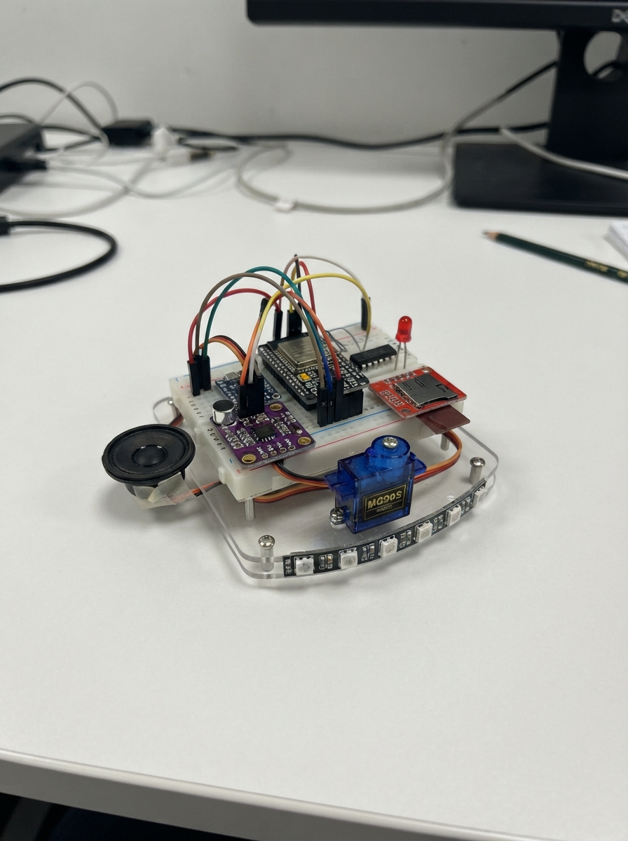
HypeBeat is a Wi-Fi-connected robot that dances and lights up in response to music and sound. Built around an ESP32 microcontroller, it combines a microphone input stage, I2S audio amplifier, servo-controlled moving head, addressable LED strip, and local web server for wireless control via smartphone or computer.
This guide provides a complete wiring diagram, parts list, and step-by-step assembly instructions to build HypeBeat from scratch. The included firmware enables standalone operation with a local Wi-Fi hotspot, music playback from microSD card, real-time audio reactivity, and web-based control of movement, lighting, and playback modes. Builders will learn audio signal conditioning, I2S audio interfacing, servo control, addressable LED programming, and embedded web server development on the ESP32.
Wiring diagram

Gather all the parts
Assemble it in 8 steps
1. Set the buck converter before connecting the robot
With the battery disconnected, turn the small adjustment screw on buck_1 while measuring its output with a multimeter. Set VOUT+ and VOUT- to exactly 5.0 V before connecting any robot electronics.
- Use the exposed VOUT+ and VOUT- screw terminals for the measurement.
- Do not connect the ESP32, servos, LEDs, or amplifier until the output is 5.0 V — a higher setting can damage them.
2. Build the protected battery lead
Connect battery_1 BAT+ to fuse_1 IN, fuse_1 OUT to switch_1 IN, switch_1 OUT to the unstriped ANODE end of diode_1, then connect the striped CATHODE end to buck_1 VIN+. Connect battery_1 BAT- and buck_1 VIN- to the shared GND return. This makes the fuse protect against shorts, the switch turn the robot off, and the diode protect against an accidentally reversed battery.
- Use thick, short wires for this battery path: red for positive and black for ground.
- Keep the battery disconnected while soldering. Never short the two battery wires together — the cells and wires can become dangerously hot.
3. Make the 5 V power rail
Run buck_1 VOUT+ to the 5 V rail and buck_1 VOUT- to the GND rail. Put rail_cap_1 across these rails: its long positive lead to 5 V and its striped negative lead to GND. Put amp_cap_1 the same way across 5 V and GND physically beside amp_1.
- Keep the amplifier capacitor leads short because it supplies the quick bursts needed during loud music.
- Make sure each capacitor's striped negative lead goes to GND — reversed electrolytic capacitors can fail or burst.
4. Connect the ESP32, SD card, and microphone
Power the ESP32 DevKit from the 5 V rail through its 5V/VIN pin and connect its GND to the shared GND rail. Connect sd_module_1 VCC to 3V3, GND to GND, MISO to GPIO19 (data), MOSI to GPIO23 (data), SCK to GPIO18 (clock), and CS to GPIO4 (select). Connect mic_1 VCC to 3V3 (power), GND to GND (ground), and OUT to GPIO34 (sound signal). Connect mic_filter_1 between that same OUT/GPIO34 signal and GND.
- Use a 3.3 V-compatible microSD module. Format the card as FAT32 before inserting it.
- Do not power a bare 3.3 V SD breakout from 5 V — that can damage the card or module.
5. Wire audio and the speaker
Connect amp_1 VIN to 5 V (power) and GND to GND (ground). Connect amp_1 BCLK to GPIO26 (audio clock), LRC to GPIO25 (audio timing), and DIN to GPIO27 (audio data). Connect amp_1 SPK+ directly to speaker_1 POS and amp_1 SPK- directly to speaker_1 NEG.
- Use two separate wires from the amplifier to the speaker.
- Do not connect either speaker wire to GND — the amplifier's SPK+ and SPK- terminals are both active outputs.
6. Wire the moving head
Connect each MG90S red VCC wire to 5 V and each brown or black GND wire to GND. Connect GPIO32 through servo_pan_resistor_1 to pan_servo_1 SIG, and GPIO33 through servo_tilt_resistor_1 to tilt_servo_1 SIG. Mount pan_servo_1 so it turns the head left and right, then mount tilt_servo_1 on that moving bracket to nod the head up and down.
- Fit the servo horns only after the firmware has centered both servos at 90 degrees.
- Servos draw large current spikes; never power either servo from the ESP32's 3.3 V pin.
7. Wire the light strip and Wi-Fi indicator
Connect led_strip_1 VCC to 5 V and GND to GND. Connect level_shifter_1 VCC to 5 V, GND to GND, and 1OE to GND so its output stays enabled. Connect GPIO21 to 1A, then connect 1Y through led_data_resistor_1 to the strip's DATA/DIN input. Connect GPIO13 through status_resistor_1 to status_led_1 ANODE; connect the LED's shorter leg to GND.
- Follow the arrows printed on the LED strip: connect to DIN, not DOUT.
- Make sure the LED's long leg is on the resistor side and its short leg is on GND — swapped LED polarity prevents it from lighting.
8. Inspect before first power-up
With the switch off, check that all modules share the same GND rail and that no bare positive wire can touch ground. Insert the FAT32 microSD card, place the microphone away from the speaker to reduce squealing feedback, then switch the robot on.
- The status LED should light when the robot creates its Wi-Fi network.
- If anything becomes hot, smells unusual, or the LEDs flicker badly, switch off immediately and recheck the 5 V rail and all GND connections.
Review all connections
1. Connections between "battery_1" and "ESP32"
2. Connections between "fuse_1" and "ESP32"
3. Connections between "switch_1" and "ESP32"
4. Connections between "diode_1" and "ESP32"
5. Connections between "buck_1" and "ESP32"
6. Connections between "rail_cap_1" and "ESP32"
7. Connections between "amp_cap_1" and "ESP32"
8. Connections between "mic_1" and "ESP32"
9. Connections between "mic_filter_1" and "ESP32"
10. Connections between "amp_1" and "ESP32"
11. Connections between "pan_servo_1" and "ESP32"
12. Connections between "servo_pan_resistor_1" and "ESP32"
13. Connections between "tilt_servo_1" and "ESP32"
14. Connections between "servo_tilt_resistor_1" and "ESP32"
15. Connections between "led_strip_1" and "ESP32"
16. Connections between "level_shifter_1" and "ESP32"
17. Connections between "led_data_resistor_1" and "ESP32"
18. Connections between "status_resistor_1" and "ESP32"
19. Connections between "status_led_1" and "ESP32"
20. Connections between "sd_module_1" and "ESP32"
Deploy the firmware
#include <Arduino.h>
#include <WiFi.h>
#include <WebServer.h>
#include <SPI.h>
#include <SD.h>
#include <ESP32Servo.h>
#include <Adafruit_NeoPixel.h>
#include <driver/i2s.h>

// HypeBeat standalone local-control firmware.
// CLOUD_HOOK marks the non-blocking locations for a future cloud database client.
const char *AP_SSID = "HypeBeat-Control";
const char *AP_PASSWORD = "hypebeat123"; // Change before demonstrating publicly.
constexpr uint8_t MIC_PIN=34, I2S_BCLK_PIN=26, I2S_LRCK_PIN=25, I2S_DOUT_PIN=27;
constexpr uint8_t PAN_SERVO_PIN=32, TILT_SERVO_PIN=33, LED_DATA_PIN=21, STATUS_LED_PIN=13;
constexpr uint8_t SD_CS_PIN=4, SD_SCK_PIN=18, SD_MISO_PIN=19, SD_MOSI_PIN=23, PIXELS=8;

WebServer server(80); SPIClass sdSPI(VSPI); Servo panServo, tiltServo;
Adafruit_NeoPixel strip(PIXELS, LED_DATA_PIN, NEO_GRB+NEO_KHZ800);
File wav; File uploadFile; bool sdReady=false, playing=false, session=true, lights=true;
uint8_t bright=128, rr=120, gg=0, bb=255; String mode="groove", current=""; unsigned long lastMove=0;

uint16_t le16(const uint8_t *p){return p[0]|(p[1]<<8);} uint32_t le32(const uint8_t *p){return p[0]|(p[1]<<8)|(p[2]<<16)|(p[3]<<24);}
String safeName(String n){int p=n.lastIndexOf('/');if(p>=0)n=n.substring(p+1);String s;for(size_t i=0;i<n.length();i++){char c=n[i];if(isAlphaNumeric(c)||c=='.'||c=='_'||c=='-')s+=c;}return s.length()?s:"music.wav";}
void showLights(){strip.setBrightness(bright);uint32_t c=lights?strip.Color(rr,gg,bb):0;for(int i=0;i<PIXELS;i++)strip.setPixelColor(i,c);strip.show();}
void stopAudio(){if(wav)wav.close();playing=false;}
bool beginWav(String requested){stopAudio();String p=requested.startsWith("/")?requested:"/"+requested;if(!sdReady||!SD.exists(p))return false;wav=SD.open(p);uint8_t h[44];if(wav.read(h,44)!=44||memcmp(h,"RIFF",4)||memcmp(h+8,"WAVE",4)||memcmp(h+12,"fmt ",4)||memcmp(h+36,"data",4)){wav.close();return false;}uint16_t format=le16(h+20),channels=le16(h+22),bits=le16(h+34);uint32_t rate=le32(h+24);if(format!=1||channels>2||bits!=16||rate<8000||rate>48000){wav.close();return false;}i2s_set_clk(I2S_NUM_0,rate,I2S_BITS_PER_SAMPLE_16BIT,channels==2?I2S_CHANNEL_STEREO:I2S_CHANNEL_MONO);current=p;playing=true;return true;}
void feedAudio(){if(!playing)return;static uint8_t input[512];int n=wav.read(input,sizeof(input));if(n<=0){stopAudio();return;}size_t done=0;i2s_write(I2S_NUM_0,input,n,&done,0);}
String listFiles(){String out="[";bool first=true;if(sdReady){File root=SD.open("/");File f=root.openNextFile();while(f){String n=f.name(),low=n;low.toLowerCase();if(!f.isDirectory()&&low.endsWith(".wav")){if(!first)out+=',';out+='\"'+n+'\"';first=false;}f.close();f=root.openNextFile();}root.close();}return out+"]";}
void sendState(){String out="{\"sdReady\":"+String(sdReady?"true":"false")+",\"playing\":"+String(playing?"true":"false")+",\"ip\":\""+WiFi.softAPIP().toString()+"\",\"file\":\""+current+"\"}";server.send(200,"application/json",out);}
void changeControl(){if(server.hasArg("lights"))lights=server.arg("lights")=="1";if(server.hasArg("session"))session=server.arg("session")=="1";if(server.hasArg("brightness"))bright=constrain(server.arg("brightness").toInt(),0,255);if(server.hasArg("r"))rr=constrain(server.arg("r").toInt(),0,255);if(server.hasArg("g"))gg=constrain(server.arg("g").toInt(),0,255);if(server.hasArg("b"))bb=constrain(server.arg("b").toInt(),0,255);if(server.hasArg("mode"))mode=server.arg("mode");showLights();/* CLOUD_HOOK: publish current controls */sendState();}
void receiveUpload(){HTTPUpload &u=server.upload();if(!sdReady)return;if(u.status==UPLOAD_FILE_START){String p="/"+safeName(u.filename);if(SD.exists(p))SD.remove(p);uploadFile=SD.open(p,FILE_WRITE);}else if(u.status==UPLOAD_FILE_WRITE&&uploadFile)uploadFile.write(u.buf,u.currentSize);else if((u.status==UPLOAD_FILE_END||u.status==UPLOAD_FILE_ABORTED)&&uploadFile)uploadFile.close();}
void moveHead(){if(!session||mode=="idle"){panServo.write(90);tiltServo.write(90);return;}if(millis()-lastMove<50)return;lastMove=millis();int lo=4095,hi=0;for(int i=0;i<24;i++){int x=analogRead(MIC_PIN);lo=min(lo,x);hi=max(hi,x);}int maxAngle=mode=="party"?48:26;int a=constrain(map(hi-lo,10,900,2,maxAngle),2,maxAngle);panServo.write(constrain(90+random(-a,a+1),35,145));tiltServo.write(constrain(90+a/2,55,125));}
void root(){const char page[] PROGMEM=R"HTML(<!doctype html><html><meta name="viewport" content="width=device-width,initial-scale=1"><style>body{font-family:Arial;background:#181020;color:#fff;margin:20px}section{border:1px solid #8040a0;margin:10px 0;padding:10px;border-radius:8px}button,input,select{font-size:16px;margin:3px;padding:7px}button{background:#8040df;color:#fff;border:0;border-radius:5px}</style><h1>HypeBeat local control</h1><p id="s">Loading</p><section><b>Music — 16-bit PCM WAV only in this build</b><form action="/upload" method="post" enctype="multipart/form-data"><input type="file" name="music" accept="audio/wav"><button>Upload WAV</button></form><select id="f"></select><button onclick="post('/play?file='+encodeURIComponent(f.value))">Play</button><button onclick="post('/stop')">Stop</button></section><section><b>Lights</b><input id="c" type="color" value="#7800ff"><input id="br" type="range" min="0" max="255" value="128"><label><input id="on" type="checkbox" checked>On</label><button onclick="light()">Apply</button></section><section><b>Movement</b><select id="m"><option value="idle">Idle</option><option value="groove" selected>Groove</option><option value="party">Party</option></select><label><input id="se" type="checkbox" checked>React to sound</label><button onclick="post('/control?session='+(se.checked?1:0)+'&mode='+m.value)">Apply</button></section><script>async function post(x){await fetch(x,{method:'POST'});refresh()}async function refresh(){let x=await(await fetch('/state')).json();s.textContent='Open http://'+x.ip+' | SD '+(x.sdReady?'ready':'missing')+(x.playing?' | playing '+x.file:'');let a=await(await fetch('/files')).json();f.innerHTML=a.map(x=>'<option>'+x+'</option>').join('')}function light(){let x=c.value;post('/control?lights='+(on.checked?1:0)+'&brightness='+br.value+'&r='+parseInt(x.slice(1,3),16)+'&g='+parseInt(x.slice(3,5),16)+'&b='+parseInt(x.slice(5,7),16))}refresh();setInterval(refresh,3000)</script></html>)HTML";server.send(200,"text/html",page);}
void setup(){Serial.begin(115200);pinMode(STATUS_LED_PIN,OUTPUT);strip.begin();showLights();panServo.setPeriodHertz(50);tiltServo.setPeriodHertz(50);panServo.attach(PAN_SERVO_PIN,500,2400);tiltServo.attach(TILT_SERVO_PIN,500,2400);sdSPI.begin(SD_SCK_PIN,SD_MISO_PIN,SD_MOSI_PIN,SD_CS_PIN);sdReady=SD.begin(SD_CS_PIN,sdSPI,10000000);i2s_config_t c={.mode=(i2s_mode_t)(I2S_MODE_MASTER|I2S_MODE_TX),.sample_rate=44100,.bits_per_sample=I2S_BITS_PER_SAMPLE_16BIT,.channel_format=I2S_CHANNEL_FMT_RIGHT_LEFT,.communication_format=I2S_COMM_FORMAT_STAND_MSB,.intr_alloc_flags=0,.dma_buf_count=8,.dma_buf_len=256,.use_apll=false,.tx_desc_auto_clear=true,.fixed_mclk=0};i2s_pin_config_t p={.bck_io_num=I2S_BCLK_PIN,.ws_io_num=I2S_LRCK_PIN,.data_out_num=I2S_DOUT_PIN,.data_in_num=I2S_PIN_NO_CHANGE};i2s_driver_install(I2S_NUM_0,&c,0,nullptr);i2s_set_pin(I2S_NUM_0,&p);WiFi.mode(WIFI_AP);WiFi.softAP(AP_SSID,AP_PASSWORD);digitalWrite(STATUS_LED_PIN,HIGH);server.on("/",HTTP_GET,root);server.on("/state",HTTP_GET,sendState);server.on("/files",HTTP_GET,[](){server.send(200,"application/json",listFiles());});server.on("/control",HTTP_POST,changeControl);server.on("/play",HTTP_POST,[](){if(!server.hasArg("file")||!beginWav(safeName(server.arg("file"))))server.send(400,"text/plain","Use a 16-bit PCM WAV file");else sendState();});server.on("/stop",HTTP_POST,[](){stopAudio();sendState();});server.on("/upload",HTTP_POST,[](){if(uploadFile)uploadFile.close();server.send(200,"text/plain","Upload complete");},receiveUpload);server.begin();}
void loop(){server.handleClient();feedAudio();moveHead();/* CLOUD_HOOK: database polling or subscription */}
Remix this project
Make it yours in one click
Open a full copy of this project in your own Schematik workspace — diagram, code, parts, and assembly steps included. Swap the sensor, add features, or redesign the whole thing with AI. The author's original stays untouched.