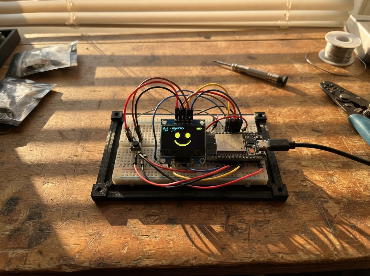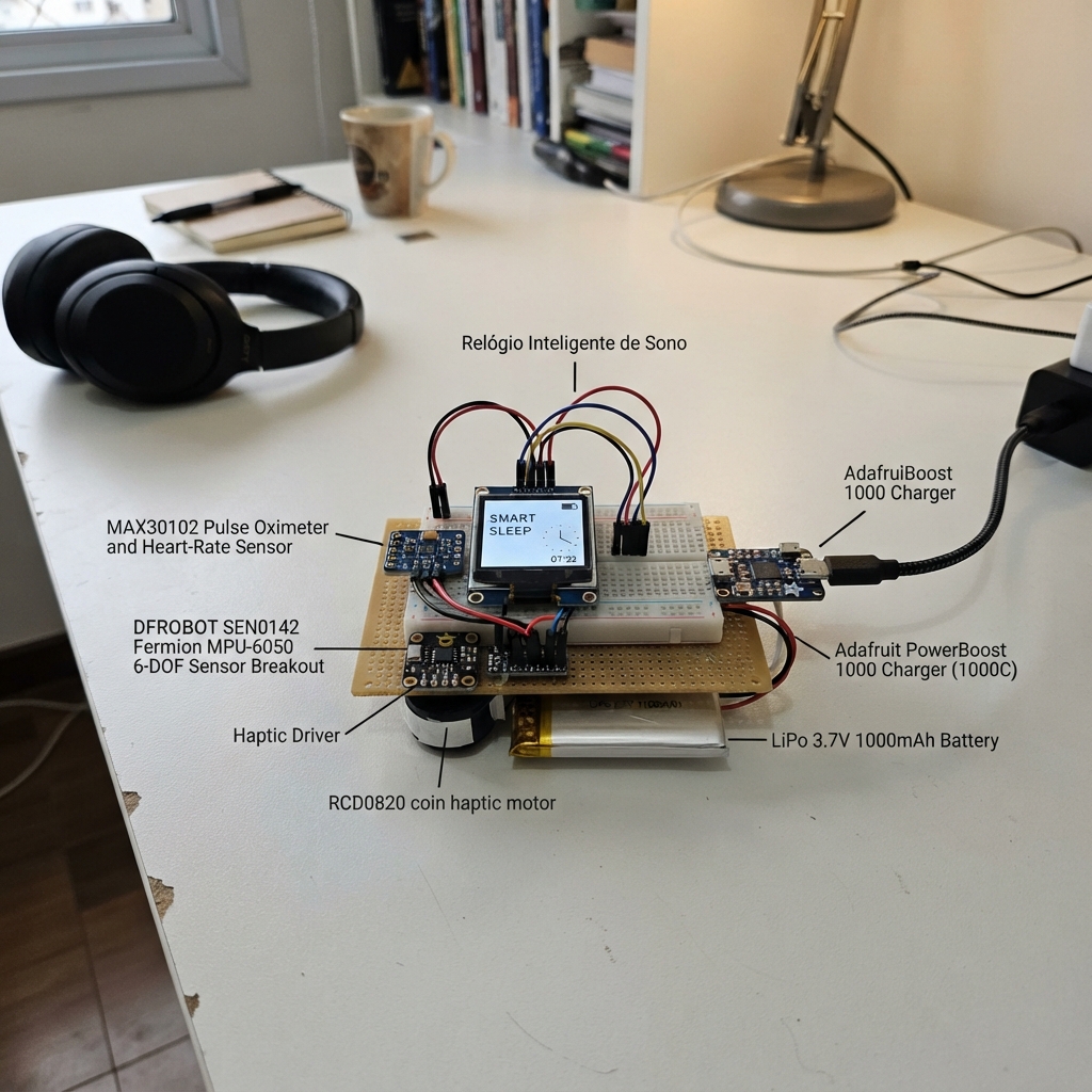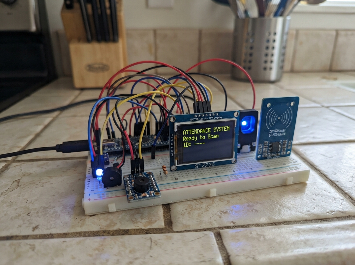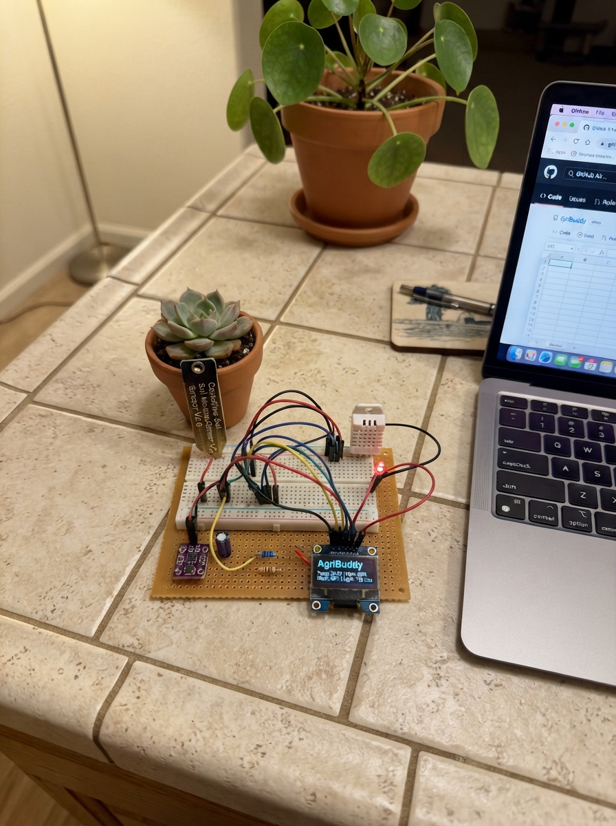
AgriBuddy is a plant monitoring system built around an ESP32 that tracks soil moisture, temperature, and light levels to help growers understand their plants' environment. The system uses a capacitive soil moisture sensor, DHT22 temperature and humidity sensor, and BH1750 light sensor, with readings displayed on a small OLED screen. All sensors connect via I2C and analog inputs for clean, organized wiring.
This guide provides a complete wiring diagram, parts list, and step-by-step assembly instructions starting from breadboard setup through final power distribution. The included firmware handles sensor commissioning, I2C device discovery, and raw data logging to the serial monitor, giving makers a solid foundation to build custom monitoring and alert logic for their specific plants and growing conditions.
Wiring diagram
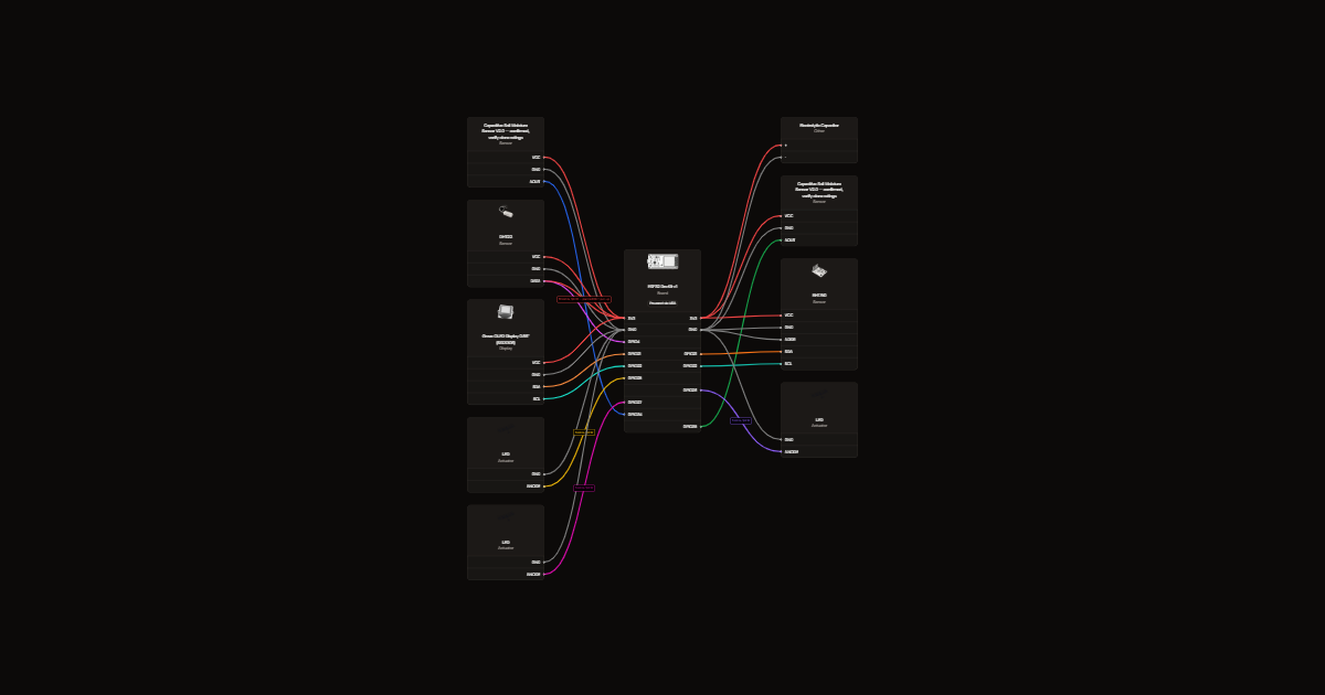
Gather all the parts
Assemble it in 11 steps
1. Identify confirmed and planned materials
Confirmed: ESP32 DevKit V1, two capacitive V2.0 moisture sensors, NPK probe, MAX485-style converter, unverified below-9V power module, breadboard and jumpers. Power bank is proposed. Planned: DHT22, BH1750, Grove 0.66-inch SSD1306, 10 uF capacitor rated at least 10 V, 10 kohm DHT pull-up and inline USB switch. Three LEDs with individual 1 kohm resistors are optional. NPK and converter are deliberately excluded from the connectable circuit until verified.
2. Diagram 1 — USB power and breadboard
Power bank USB socket → plug-in inline USB ON/OFF switch → intact USB cable → ESP32 USB socket. No cable cutting and no buck converter. ESP32 3V3 → breadboard positive rail; ESP32 GND → negative rail. Capacitor + → positive rail; striped minus lead → negative rail, close to ESP32. Never put both capacitor leads in one connected row.
- Use regulated 5 V USB only. Do not feed the unverified power module into USB, 3V3 or VIN.
3. Check the breadboard before sensors
With all power removed, use a meter to identify five-hole connected rows and any split rail sections. Bridge positive to positive and negative to negative only where needed. Put ESP32 across the center gap only if its width leaves usable holes; otherwise use header jumpers to the breadboard. Follow printed pin names, not assumed row positions. Switch USB on with sensors disconnected and measure approximately 3.3 V between rails. Switch off again.
- Power bank may turn off automatically at low current. Test continuous operation. Disconnect power bank before connecting PC USB for Deploy.
4. Diagram 2 — independent soil readings
Each sensor VCC → 3.3 V rail (red), GND → ground rail (black). Sensor 1 AOUT → GPIO34; sensor 2 AOUT → GPIO35 (yellow signals). GPIO34/35 are input-only ADC1 inputs and have no internal pull-ups. Verify each clone permits 3.3 V supply and measure AOUT with ESP32 signal wires disconnected: it must remain within 0–3.3 V. ADC may saturate near the upper end even with attenuation. Calibrate each probe separately using dry and wet reference readings; keep electronics above soil/water.
5. Diagram 3 — planned temperature and light
Bare DHT22 facing its grille, legs downward: pin 1 VCC → 3V3; pin 2 DATA → GPIO4 (green); pin 3 NC left disconnected; pin 4 GND → ground. 10 kohm resistor between DATA and 3V3; omit additional resistor if the chosen module already has a suitable 3.3 V pull-up. BH1750 VCC → 3V3, GND → ground, SDA → GPIO21 and SCL → GPIO22 (blue), ADDR → ground selects 0x23. Verify module markings and supply compatibility before connecting.
6. Diagram 4 — planned shared I2C OLED
Selected planned display: Grove 0.66-inch 64×48 SSD1306. Grove pin 1 SCL → GPIO22; pin 2 SDA → GPIO21; pin 3 VCC → 3V3; pin 4 GND → ground. These SDA/SCL wires join the same nets as BH1750, not a series connection. OLED default 0x3C (alternate 0x3D) does not conflict with BH1750 0x23 (alternate 0x5C). All host pull-ups must go to 3.3 V, never 5 V. Check existing bus pull-ups before adding any. Firmware only scans I2C; it does not drive the display or read planned environmental sensors.
7. Diagram 5 — NPK branch, do not connect yet
PROVISIONAL ONLY: verified external supply + → NPK power +; supply − → NPK power −. NPK A → converter A; NPK B → converter B. For a verified non-isolated interface, connect supply − / NPK reference ground / converter GND / ESP32 GND; do not invent a separate reference wire if the sensor has none. MAX485 VCC needs verified regulated 5 V, not 3.3 V and not the NPK higher-voltage rail. DI → GPIO17; RO → protective 5V-to-3.3V receiver buffer → GPIO16. Tie DE and active-low /RE together → GPIO18, with recommended 10 kohm pull-down to ground. LOW receives; HIGH transmits; wait for UART transmission completion before LOW. Direct DI/DE control is conditional on verifying genuine MAX485 TTL thresholds and absence of module pull-ups to 5 V. Otherwise level-shift those too.
- VERIFY BEFORE POWERING: exact sensor model/manual, wire functions, permitted voltage, current and polarity; module output voltage/current/regulation; converter chip and schematic; isolation/reference requirements; baud, parity, slave address, function and register map. The reported 5–30 V label is not enough to approve the supply.
- Never connect A/B or unprotected 5 V RO to ESP32. Do not power one side of a non-isolated interface while the other is off unless protection permits it.
8. Diagram 6 — optional indicators
GPIO25 → 1 kohm resistor → green anode; GPIO26 → separate 1 kohm resistor → yellow anode; GPIO27 → separate 1 kohm resistor → red anode. All cathodes → GND. Long LED lead usually indicates anode; flat rim/short lead usually cathode; verify before wiring. 1 kohm limits current to at most 3.3 mA; actual current is (3.3 V minus LED forward voltage)/1000. Choose LED specifications for visible operation at this small current. Intended meanings: green successful readings, yellow processing, red error; commissioning firmware does not implement these indicators.
9. Diagram 7 — combined wiring and power distribution
USB 5 V → ESP32 onboard regulator → 3.3 V rail → soil1, soil2, DHT22, BH1750 and OLED, with capacitor in parallel across 3.3 V/GND. Soil AOUT → 34/35; DHT DATA → 4; shared SDA/SCL → 21/22; optional LEDs → 25/26/27 through individual resistors. Reserved NPK UART RX/TX/control → 16/17/18; leave physically disconnected pending Diagram 5 verification. NPK external supply is a separate positive rail, never tied to 3V3. Red power, black GND, yellow analog, green digital, blue I2C, orange UART, purple RS485 and gray direction control. Manufacturer cable colors may differ: pin labels take priority.
10. Additional protection and power budget
Add separately recommended protection, not already-owned materials: a unidirectional 5V-tolerant input buffer powered at 3.3 V with power-off protection for RO, local 100 nF converter decoupling if absent, and appropriate external-supply fuse/ESD protection for exposed cable runs after ratings are known. Check onboard RS485 termination and bias before adding them; termination belongs only at two bus ends. Do not blindly stack 120 ohm resistors. Verify power bank current rating, board regulator headroom and total actual loads; no runtime or current budget can be certified from current information.
11. Final pre-power safety checklist
Disconnect USB and external supply. Check capacitor polarity, LED resistor per LED, no rail shorts, correct split-rail bridges, module supply labels, no GPIO above 3.3 V, and no NPK positive supply tied to ESP32 rail. Check converter protection separately before enabling its branch. Power in stages: ESP32 only, then each moisture sensor, then planned sensors individually, then shared I2C. Recheck voltages at each stage. Leave NPK disconnected until its verification list is complete.
Review all connections
1. Connections between "soil1" and "ESP32"
2. Connections between "soil2" and "ESP32"
3. Connections between "dht" and "ESP32"
4. Connections between "pullup" and "ESP32"
5. Connections between "light" and "ESP32"
6. Connections between "oled" and "ESP32"
7. Connections between "bulk" and "ESP32"
8. Connections between "rg" and "ESP32"
9. Connections between "green" and "ESP32"
10. Connections between "ry" and "ESP32"
11. Connections between "yellow" and "ESP32"
12. Connections between "rr" and "ESP32"
13. Connections between "red" and "ESP32"
Deploy the firmware
#include <Arduino.h>
#include <Wire.h>
// Commissioning only. No invented NPK protocol or soil nutrient estimates.
void setup() {
 Serial.begin(115200);
 Wire.begin(21,22);
 analogReadResolution(12);
 analogSetPinAttenuation(34, ADC_11db);
 analogSetPinAttenuation(35, ADC_11db);
 Serial.println("AgriBuddy commissioning: NPK disabled; raw moisture is not calibrated percent.");
 for (uint8_t a=1;a<127;a++) { Wire.beginTransmission(a); if(Wire.endTransmission()==0) Serial.printf("I2C found 0x%02X\n",a); }
}
void loop() {
 Serial.printf("Soil1=%lu mV Soil2=%lu mV; NPK UNVERIFIED\n",(unsigned long)analogReadMilliVolts(34),(unsigned long)analogReadMilliVolts(35));
 delay(2500);
}
Remix this project
Make it yours in one click
Open a full copy of this project in your own Schematik workspace, diagram, code, parts, and assembly steps included. Swap the sensor, add features, or redesign the whole thing with AI. The author's original stays untouched.