Community project
Animated OLED Eyes
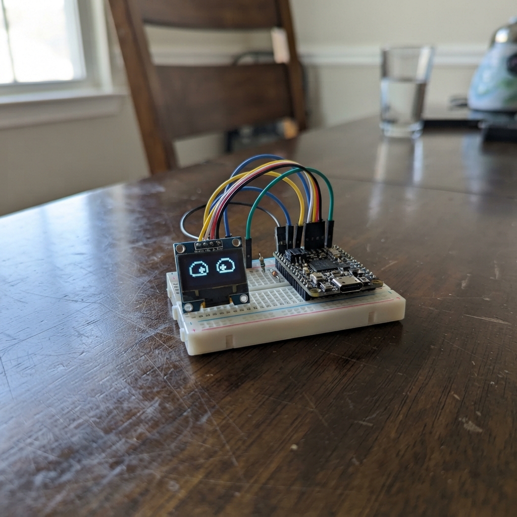
This project brings a pair of animated eyes to life on a small OLED display, complete with realistic pupil movement and blinking. The eyes follow a smooth animation cycle, looking left and right while occasionally blinking, creating an engaging character display that responds to a simple animation loop.
Built around an Arduino Uno and a compact 0.66-inch OLED screen, this guide provides everything needed to assemble and program the project. Readers will receive a complete wiring diagram, parts list, and ready-to-upload firmware that handles all the eye animation logic, along with step-by-step assembly instructions to get the eyes animating in minutes.
Wiring diagram

Gather all the parts
Assemble it in 4 steps
1. Place the Nano and screen
With the Nano unplugged, put the Nano and the small four-pin OLED screen on a breadboard or non-metal table. Find the screen pins labelled VCC, GND, SDA, and SCL.
- The screen must be a 0.96-inch, 128×64 I²C SSD1306 module marked 3.3–5 V or 5 V compatible.
- Do not move wires while the Nano is powered, because a misplaced wire can short the power pins.
2. Connect the screen power wires
Connect OLED VCC to Nano 5V (power). Connect OLED GND to Nano GND (ground). These two wires give the 3.3–5 V compatible screen power.
- Use a red wire for VCC and a black wire for GND if you have them.
- Make sure VCC and GND are not swapped — swapped power can damage the screen.
3. Connect the screen data wires
Connect OLED SDA to Nano A4 (data). Connect OLED SCL to Nano A5 (data). These two wires carry the drawing commands that make the eyes move.
- A4 and A5 are printed beside the Nano's analogue-pin header.
- Do not connect the OLED SDA or SCL pin straight to 5V or GND.
4. Start the eyes
Check the four screen wires, plug the Nano into USB, then press Deploy in Schematik. The eyes continuously glance left, centre, and right, with an occasional double blink.
- If the screen stays blank, first check that SDA and SCL have not been swapped.
- Only use the direct screen wiring shown here with an OLED marked 3.3–5 V or 5 V compatible.
Review all connections
1. Connections between "oled_1" and "Arduino"
Deploy the firmware
#include <Arduino.h>
#include <Wire.h>
#include <Adafruit_GFX.h>
#include <Adafruit_SSD1306.h>

void drawEye(int centerX, int pupilX, bool blinking);
void drawFace();

const uint8_t SCREEN_WIDTH = 128;
const uint8_t SCREEN_HEIGHT = 64;
const uint8_t OLED_ADDRESS = 0x3C;
const int I2C_SDA_PIN = 18;  // Nano A4
const int I2C_SCL_PIN = 19;  // Nano A5
const unsigned long FRAME_INTERVAL_MS = 50UL;

Adafruit_SSD1306 display(SCREEN_WIDTH, SCREEN_HEIGHT, &Wire, -1);
unsigned long lastFrameMs = 0;
uint16_t frameNumber = 0;

void drawEye(int centerX, int pupilX, bool blinking) {
  if (blinking) {
    display.drawFastHLine(centerX - 23, 32, 47, SSD1306_WHITE);
    return;
  }

  display.fillRoundRect(centerX - 24, 16, 48, 34, 15, SSD1306_WHITE);
  display.fillCircle(pupilX, 33, 9, SSD1306_BLACK);
  display.fillCircle(pupilX - 3, 29, 2, SSD1306_WHITE);
}

void drawFace() {
  uint16_t cycleFrame = frameNumber % 180;
  bool blinking = (cycleFrame >= 150 && cycleFrame < 156) ||
                  (cycleFrame >= 160 && cycleFrame < 164);
  int8_t lookOffset = 0;

  if (cycleFrame < 45) {
    lookOffset = -6;
  } else if (cycleFrame < 90) {
    lookOffset = 0;
  } else if (cycleFrame < 135) {
    lookOffset = 6;
  }

  display.clearDisplay();
  drawEye(35, 35 + lookOffset, blinking);
  drawEye(93, 93 + lookOffset, blinking);
  display.display();
}

void setup() {
  Wire.begin();
  if (!display.begin(SSD1306_SWITCHCAPVCC, OLED_ADDRESS)) {
    for (;;) {
    }
  }
  drawFace();
}

void loop() {
  unsigned long now = millis();
  if (now - lastFrameMs >= FRAME_INTERVAL_MS) {
    lastFrameMs = now;
    frameNumber++;
    drawFace();
  }
}
Remix this project
Make it yours in one click
Open a full copy of this project in your own Schematik workspace — diagram, code, parts, and assembly steps included. Swap the sensor, add features, or redesign the whole thing with AI. The author's original stays untouched.