Community project
Odradek Motion Light Controller
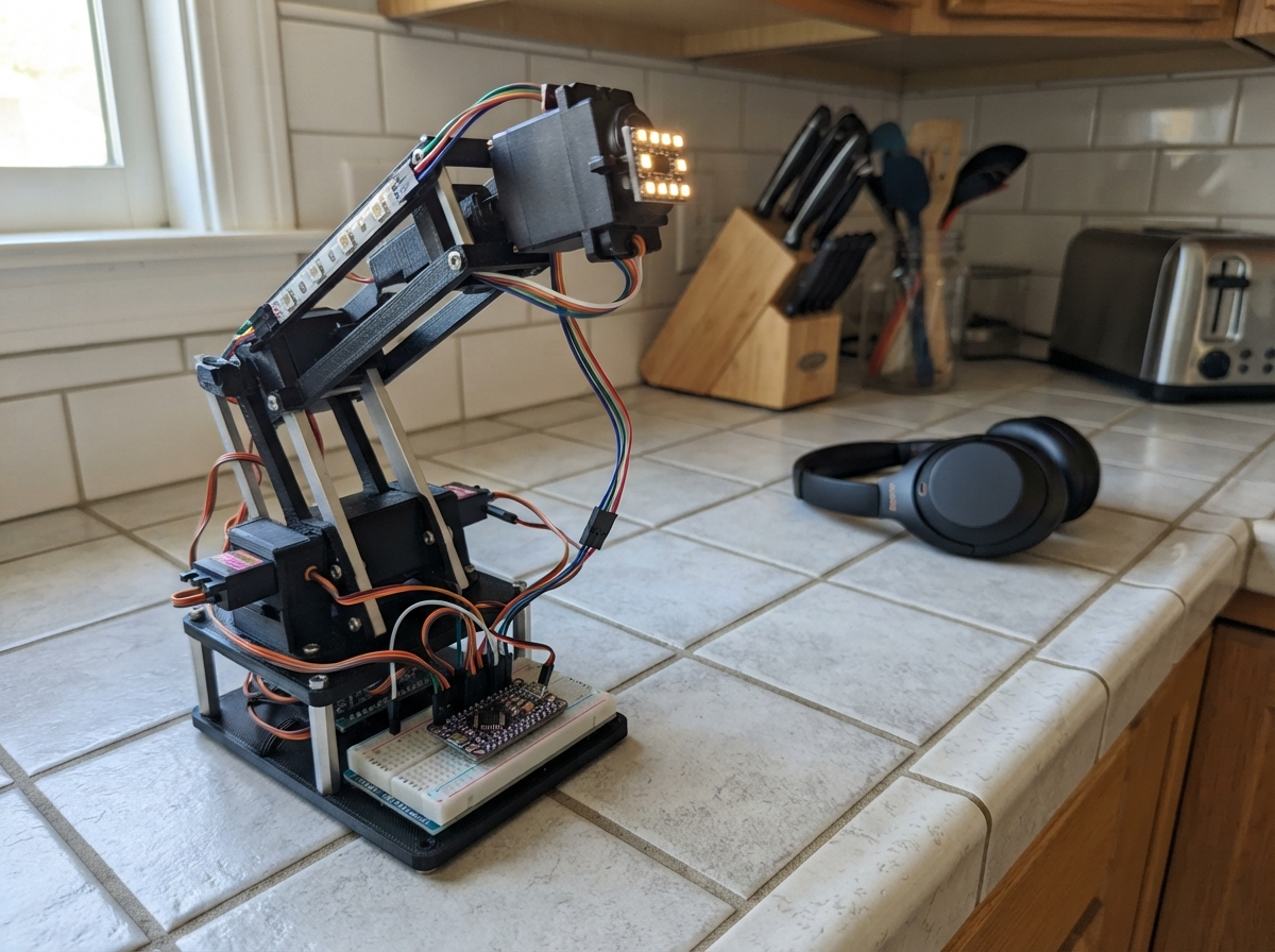
The Odradek Motion Light Controller brings articulated movement and dynamic lighting to a five-arm mechanism with independent head positioning. This guide covers building a PCA9685-based servo controller that drives five arm servos and a 270-degree head servo, along with four independently dimmable RGB channels and a status indicator LED, all coordinated by an Arduino Uno.
Builders will receive a complete wiring diagram, detailed parts list with power distribution guidance, Arduino firmware with pose presets and safety limits, and step-by-step assembly instructions including mechanism alignment and unloaded testing. The controller supports multiple head scanning modes and arm motion alerts, with all servo endpoints calibrated for safe operation.
Wiring diagram

Gather all the parts
Assemble it in 6 steps
1. Verify the assumed parts before connecting power
This is a new reference circuit, not a recovered existing Odradek circuit. Use exactly five arm positional servos and one head positional servo approved for 6 V, 50 Hz and 5 V control. For full head travel, buy the genuine 270-degree positional version, never a continuous-rotation servo. Existing arm torque, stall current, LED voltage and current are unknown; verify them before connecting. The five RGB strips are assumed 12 V common-positive with built-in resistors; the extra blue LED is an ordinary low-current LED.
- Never apply the assumed voltages to unverified existing parts. A standard 180-degree servo cannot turn 270 degrees.
2. Build separate fused power distribution
With supplies unplugged, connect supply12 PLUS through its fuse to the 12 V lighting rail; supply6 PLUS through its fuse to the 6 V servo rail. Join both MINUS terminals, UNO GND and PCA GND at a common ground distribution point. Power UNO through USB only. Keep all positive rails separate. Connect the capacitor PLUS to 6 V and MINUS to ground. Use heavy distribution wires and screw terminals for servo current, not UNO pins or breadboard rails. Use enclosed low-voltage adapters only, no mains wiring.
- Size the 6 V supply from the sum of all six actual stall currents plus 25% margin. Size 12 V supply from full-white RGB current plus LED driver input and blue LED current, plus 25%. Fuse values must protect the actual wire gauge and fit the load. The power estimate is a provisional planning budget, not a measured load.
- Do not connect 6 V or 12 V to UNO 5V. Reversing the capacitor can make it burst.
3. Connect the servo signal controller
PCA VCC to UNO 5V (logic), SDA to A4 (data), SCL to A5 (clock), GND to common ground, and VPLUS to 6 V. OE to D2 (output enable), with its own 10 kohm pull-up to 5V. Leave address jumpers open for 0x40. Connect CH0 through CH4 signal pins to arm servos 1 through 5; CH5 signal to head servo 6. Each servo gets 6 V and ground directly from external distribution. Do not pass all motor current through the breakout's small header tracks.
- OE disables signals, not motor power. Have an accessible supply disconnect. An unsupported mechanism can fall when signals or power are removed.
4. Build the four MOSFET dimmer channels
For each IRLZ44N, text facing you and legs down: left is gate, middle is drain, right is source; metal tab is also drain. Source goes to common ground. D3 through its 330 ohm resistor to qR gate; D5 through 330 ohm to qG gate; D6 through 330 ohm to qB gate; D9 through 330 ohm to qBlue gate. Fit each separate 10 kohm gate pull-down to ground. Connect all five strip PLUS pads to 12 V, all R pads to qR drain, all G pads to qG drain, all B pads to qB drain. Put blue_limit 1 kohm 0.5 W between 12 V and blue LED anode; blue cathode goes to qBlue drain.
- All strip sections share the same colour; conventional analog strips cannot animate individual LEDs. Each section contains its own current-limiting resistors. The separate blue LED has its own external series resistor.
- MOSFETs switch the loads, not GPIO pins. Check actual channel current, MOSFET heat and connectors under full load; fit isolated heatsinks if needed. Never join drain tabs together.
5. Wire the independent white LED driver
Use a white emitter rated for at least 350 mA continuous on a suitable heatsink. LDD-350L VINP to 12 V; VINM to common ground; OUTP to white anode; OUTM to white cathode. DIM to D10 (approximately 490 Hz PWM), with white_pull 10 kohm to ground. Identify these names using the exact LDD package's maker drawing; do not guess physical pin orientation. Its 350 mA constant-current regulation replaces a series resistor.
- Do not connect OUTM to ground or bypass the driver. Never run a power LED without its heatsink; do not look directly into the bright emitter. An unknown existing white LED may require a different current-rated driver.
6. Align and test the mechanism unloaded
Leave servo horns/linkages disconnected for the first test. With power off inspect polarity and shorts. Support the mechanism. Use firmware calibration values appropriate for the actual servos. Centre/test one servo at a time, then switch power off before installing each horn so its known folded/home command matches the resting pose. Check all five arm limits separately and allow cable slack through the entire head sweep. Do not force servo shafts manually. Only reconnect the assembled mechanism once verified free of collisions.
- Software has no position feedback and cannot prevent an initial snap if the physical pose does not match its first command. On every restart or after off, align and support the folded/home pose before enabling. Do not use hard-stop impacts or stalled servos to create clicking. The effect is a rhythmic movement, not guaranteed audible sound.
Review all connections
1. Connections between "pca" and "Arduino"
2. Connections between "servo1" and "Arduino"
3. Connections between "servo2" and "Arduino"
4. Connections between "servo3" and "Arduino"
5. Connections between "servo4" and "Arduino"
6. Connections between "servo5" and "Arduino"
7. Connections between "servo6" and "Arduino"
8. Connections between "rgb1" and "Arduino"
9. Connections between "rgb2" and "Arduino"
10. Connections between "rgb3" and "Arduino"
11. Connections between "rgb4" and "Arduino"
12. Connections between "rgb5" and "Arduino"
13. Connections between "blue_limit" and "Arduino"
14. Connections between "blue" and "Arduino"
15. Connections between "R_gate" and "Arduino"
16. Connections between "R_pull" and "Arduino"
17. Connections between "qR" and "Arduino"
18. Connections between "G_gate" and "Arduino"
19. Connections between "G_pull" and "Arduino"
20. Connections between "qG" and "Arduino"
21. Connections between "B_gate" and "Arduino"
22. Connections between "B_pull" and "Arduino"
23. Connections between "qB" and "Arduino"
24. Connections between "Blue_gate" and "Arduino"
25. Connections between "Blue_pull" and "Arduino"
26. Connections between "qBlue" and "Arduino"
27. Connections between "white_driver" and "Arduino"
28. Connections between "white_pull" and "Arduino"
29. Connections between "supply12" and "Arduino"
30. Connections between "supply12_fuse" and "Arduino"
31. Connections between "supply6" and "Arduino"
32. Connections between "supply6_fuse" and "Arduino"
33. Connections between "cap" and "Arduino"
34. Connections between "oe_pull" and "Arduino"
Deploy the firmware
#include <Arduino.h>
#include <Wire.h>
#include <math.h>
// All angles are installation-specific examples, NOT measured mechanism limits.
// Test unloaded, align horns at the folded pose, then type arm. No boot pulses.
namespace Config {
const uint8_t PCA = 0x40;
const uint8_t enablePin=2; // PCA OE active LOW
const uint32_t OSC_HZ = 25000000UL; // Measure/calibrate your PCA oscillator if needed.
const uint8_t PRESCALE = 121; // nominal 50 Hz, no Servo library/timer conflict
const float closed[5] = {90,90,90,90,90};
const float active[5] = {100,100,100,100,100};
const float opened[5] = {140,140,140,140,140};
const float armMin[5] = {70,70,70,70,70};
const float armMax[5] = {150,150,150,150,150};
const uint16_t armPulseMin[5] = {1000,1000,1000,1000,1000};
const uint16_t armPulseMax[5] = {2000,2000,2000,2000,2000};
// These pulses map to 0..180 logical degrees. Verify actual arm servo endpoints.
// Head: actual POSITIONAL servo's angle between calibrated pulse endpoints.
// A normal 180-degree servo stays 180 here. Genuine 270 variant: set span=270
// and its VERIFIED pulses (not automatically 500..2500), then safe endpoints.
const float headServoSpan = 180;
const uint16_t headPulseMin = 1000, headPulseMax = 2000;
const float headSafeMin = 60, headSafeMax = 120, headHome = 90;
// Head sweep is always bounded to <=270 degrees, even if config is mistaken.
const bool headScanMode2=false, headScanMode3=true, headScanClick=true;
const bool alertArmMotion=false;
const float poseSpeed=22, clickSpeed=40, headSpeed=8; // degrees per second
const float clickTravel=1.0f; // 0..1 of active->open distance
const uint16_t clickPauseMs=300, armStaggerMs=65, alertHalfPeriodMs=850;
const float alertTravel=3;
const uint16_t servoTickMs=20, lightTickMs=10;
// Channels: strip R,G,B; independent blue LED; independent white driver.
const uint8_t lightPins[5]={3,5,6,9,10};
struct Light { uint8_t r,g,b,stripBrightness,blue,white; };
const Light lights[5]={
 {165,220,255,255,255,240}, // mode 1 icy
 {100,180,255,180,170,150}, // mode 2 deeper blue
 {175,225,255,255,255,255}, // mode 3
 {175,225,255,255,255,255}, // mode 3.5
 {255,65,0,255,0,0}        // mode 4: no white to wash out orange
};
}
enum Mode : uint8_t {IDLE,ACTIVE,SCAN,CLICK,ALERT};
Mode mode=IDLE;
float pos[6], target[6];
uint8_t lightNow[5]={}, lightTarget[5]={};
uint16_t lastPulse[6]={};
bool enabled=false, healthy=true, outward=true, headForward=true, waiting=false;
uint32_t entered=0, phaseStart=0, pauseStart=0, lastServo=0,lastLight=0;
char command[16]; uint8_t commandLen=0; bool overflow=false;
float bounded(float v,float lo,float hi){return max(lo,min(hi,v));}
float headLo(){return bounded(Config::headSafeMin,0,min(270.0f,Config::headServoSpan));}
float headHi(){return bounded(Config::headSafeMax,headLo(),min(270.0f,Config::headServoSpan));}
bool regWrite(uint8_t reg,uint8_t val){Wire.beginTransmission(Config::PCA);Wire.write(reg);Wire.write(val);return Wire.endTransmission()==0;}
bool pulseWrite(uint8_t ch,uint16_t us){
 uint16_t ticks=(uint32_t)us* (Config::OSC_HZ/1000UL) / ((uint32_t)(Config::PRESCALE+1)*1000UL);
 Wire.beginTransmission(Config::PCA);Wire.write(0x06+4*ch);
 Wire.write(0);Wire.write(0);Wire.write(ticks&255);Wire.write(ticks>>8);
 return Wire.endTransmission()==0;
}
void stopOutputs(){digitalWrite(Config::enablePin,HIGH);regWrite(0xFD,0x10);enabled=false;}
void fail(){healthy=false;stopOutputs();Serial.println(F("I2C fault: cut servo power; inspect wiring and reset."));}
void setLighting(){
 const Config::Light &l=Config::lights[mode];
 lightTarget[0]=(uint16_t)l.r*l.stripBrightness/255;
 lightTarget[1]=(uint16_t)l.g*l.stripBrightness/255;
 lightTarget[2]=(uint16_t)l.b*l.stripBrightness/255;
 lightTarget[3]=l.blue; lightTarget[4]=l.white;
}
void selectMode(Mode m){mode=m;entered=phaseStart=millis();waiting=false;outward=true;headForward=true;setLighting();Serial.println(F("Mode selected."));}
void armsPose(const float *pose){for(uint8_t i=0;i<5;i++)target[i]=pose[i];}
void headScan(bool scan){
 if(!scan){target[5]=bounded(Config::headHome,headLo(),headHi());return;}
 if(headForward && pos[5]>=headHi()-0.01f)headForward=false;
 else if(!headForward && pos[5]<=headLo()+0.01f)headForward=true;
 target[5]=headForward?headHi():headLo();
}
void mode1FoldedIdle(){armsPose(Config::closed);headScan(false);}
void mode2FoldedActive(){armsPose(Config::active);headScan(Config::headScanMode2);}
void mode3FullScan(){armsPose(Config::opened);headScan(Config::headScanMode3);}
void mode35ArticulatedClick(uint32_t now){
 bool reached=true;
 for(uint8_t i=0;i<5;i++){
  if((uint32_t)(now-phaseStart)<(uint32_t)i*Config::armStaggerMs){reached=false;continue;}
  float end=Config::active[i]+bounded(Config::clickTravel,0,1)*(Config::opened[i]-Config::active[i]);
  target[i]=bounded(outward?end:Config::active[i],Config::armMin[i],Config::armMax[i]);
  if(fabs(pos[i]-target[i])>0.01f)reached=false;
 }
 if(reached){
  if(!waiting){waiting=true;pauseStart=now;}
  if((uint32_t)(now-pauseStart)>=Config::clickPauseMs){outward=!outward;phaseStart=now;waiting=false;}
 }
 headScan(Config::headScanClick);
}
void mode4OrangeAlert(uint32_t now){
 armsPose(Config::opened);headScan(true); // bounded sweep, ALWAYS reverses
 if(Config::alertArmMotion){
  bool twitch=((now-entered)/Config::alertHalfPeriodMs)&1;
  for(uint8_t i=0;i<5;i++)if(twitch)target[i]-=Config::alertTravel;
 }
}
void updateMotion(uint32_t now){
 if(!enabled)return;
 if((uint32_t)(now-lastServo)<Config::servoTickMs)return;
 lastServo=now; // cap step after a stall; never make a catch-up jump
 switch(mode){case IDLE:mode1FoldedIdle();break;case ACTIVE:mode2FoldedActive();break;case SCAN:mode3FullScan();break;case CLICK:mode35ArticulatedClick(now);break;case ALERT:mode4OrangeAlert(now);break;}
 for(uint8_t i=0;i<6;i++){
  target[i]=i<5?bounded(target[i],Config::armMin[i],Config::armMax[i]):bounded(target[i],headLo(),headHi());
  float step=(i==5?Config::headSpeed:(mode==CLICK?Config::clickSpeed:Config::poseSpeed))*Config::servoTickMs/1000.0f;
  float delta=target[i]-pos[i];pos[i]+=bounded(delta,-step,step);
  uint16_t us=i<5 ? Config::armPulseMin[i]+pos[i]/180.0f*(Config::armPulseMax[i]-Config::armPulseMin[i]) : Config::headPulseMin+pos[i]/Config::headServoSpan*(Config::headPulseMax-Config::headPulseMin);
  if(us!=lastPulse[i]){if(!pulseWrite(i,us)){fail();return;}lastPulse[i]=us;}
 }
 // Once pose is reached no new writes. Servos retain holding pulses/torque.
}
void updateLights(uint32_t now){
 if((uint32_t)(now-lastLight)<Config::lightTickMs)return;lastLight=now;
 for(uint8_t i=0;i<5;i++){
  if(lightNow[i]==lightTarget[i])continue;
  lightNow[i]+=lightNow[i]<lightTarget[i]?1:-1;
  analogWrite(Config::lightPins[i],lightNow[i]);
 }
}
void handleCommand(){
 if(!strcmp(command,"1")||!strcmp(command,"home")){selectMode(IDLE);}
 else if(!strcmp(command,"2"))selectMode(ACTIVE);
 else if(!strcmp(command,"3"))selectMode(SCAN);
 else if(!strcmp(command,"3.5"))selectMode(CLICK);
 else if(!strcmp(command,"4"))selectMode(ALERT);
 else if(!strcmp(command,"off")){stopOutputs();Serial.println(F("Signals OFF, load can fall. Re-align folded pose before arm."));}
 else if(!strcmp(command,"arm")){
  if(enabled){selectMode(IDLE);return;}
  if(!healthy){Serial.println(F("Reset after fixing I2C."));return;}
  stopOutputs();selectMode(IDLE);
  for(uint8_t i=0;i<6;i++){pos[i]=target[i]=i<5?Config::closed[i]:bounded(Config::headHome,headLo(),headHi());lastPulse[i]=0;}
  // Seed known aligned pose with OE still HIGH, then enable all at once.
  for(uint8_t i=0;i<6;i++){
   uint16_t us=i<5 ? Config::armPulseMin[i]+pos[i]/180.0f*(Config::armPulseMax[i]-Config::armPulseMin[i]) : Config::headPulseMin+pos[i]/Config::headServoSpan*(Config::headPulseMax-Config::headPulseMin);
   if(!pulseWrite(i,us)){fail();return;}lastPulse[i]=us;
  }
  digitalWrite(Config::enablePin,LOW);
  enabled=true;Serial.println(F("Enabled: assumes physically aligned folded/home pose."));
 }else Serial.println(F("Commands: arm, 1, 2, 3, 3.5, 4, home, off"));
}
void readSerial(){
 // Bounded work per loop prevents continuous serial traffic starving motion.
 for(uint8_t n=0;n<16 && Serial.available();n++){
  char c=Serial.read();
  if(c=='\r'||c=='\n'){
   if(overflow)Serial.println(F("Command too long."));
   else if(commandLen){command[commandLen]=0;handleCommand();}
   commandLen=0;overflow=false;
  }else if(!overflow){if(commandLen<sizeof(command)-1)command[commandLen++]=c;else overflow=true;}
 }
}
void setup(){
 digitalWrite(Config::enablePin,HIGH);pinMode(Config::enablePin,OUTPUT);
 Serial.begin(115200);
 for(uint8_t i=0;i<5;i++){digitalWrite(Config::lightPins[i],LOW);pinMode(Config::lightPins[i],OUTPUT);}
 Wire.begin();Wire.setClock(100000);Wire.setWireTimeout(25000,true);
 // Direct framework Wire driver; no external libraries required. PCA MODE1 AI,
 // MODE2 non-inverted totem-pole. Sleep before prescaler, wake then restart.
 healthy=regWrite(0x00,0x30) && regWrite(0x01,0x04) && regWrite(0xFD,0x10) && regWrite(0xFE,Config::PRESCALE) && regWrite(0x00,0x20);
 delayMicroseconds(600); // oscillator startup only, not an animation delay
 healthy=healthy && regWrite(0x00,0xA0);
 if(!healthy)fail();
 setLighting();
 Serial.println(F("Odradek: outputs disabled. Calibrate unloaded; align folded/home; type arm."));
 Serial.println(F("115200 baud; newline; 1 / 2 / 3 / 3.5 / 4 / home / off"));
}
void loop(){uint32_t now=millis();readSerial();updateMotion(now);updateLights(now);}
Remix this project
Make it yours in one click
Open a full copy of this project in your own Schematik workspace — diagram, code, parts, and assembly steps included. Swap the sensor, add features, or redesign the whole thing with AI. The author's original stays untouched.