Community project
Arduino Laser Harp
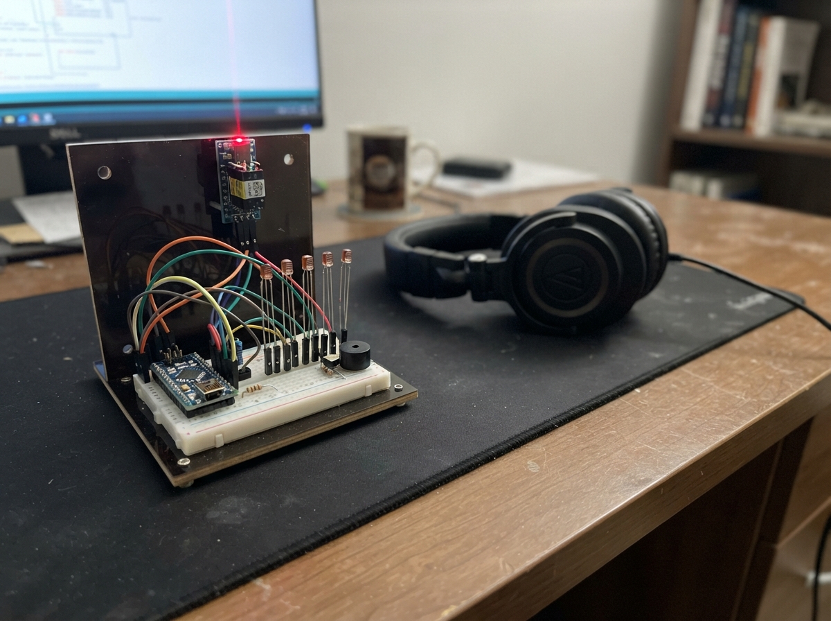
Build a playable laser harp that produces musical notes when hand or object interrupts infrared laser beams. This Arduino Uno project combines four laser modules with light sensors to create an interactive instrument that outputs different pitches through a piezo buzzer when each beam is blocked.
This guide provides a complete parts list, wiring diagram, assembly steps for safe laser positioning, calibration procedure, and Arduino firmware. Makers will learn how to use analog sensors to detect light interruption, map sensor readings to musical notes, and create real-time audio feedback with a simple buzzer.
Wiring diagram

Gather all the parts
Assemble it in 5 steps
1. Set up a safe harp frame
Make a small cardboard, wood, or 3D-printed frame with four laser positions on one side and four matching sensor positions on the opposite side. Put the beams at hand height only, aim them downward or into a non-reflective backstop, and leave enough space that your hand can block one beam at a time.
- A short, shaded enclosure around each light sensor makes it much less likely that room light will trigger notes.
- Secure each laser before applying power so its beam cannot sweep around while you work.
- Never aim a laser at eyes, people, animals, mirrors, shiny metal, windows, or traffic; reflected light can cause eye injury.
2. Place the light sensors and resistors
Put each photoresistor across a gap in the breadboard. For each sensor, connect one photoresistor leg to the Arduino 5V row, and make a shared row with its other leg, the matching 10 kΩ resistor lead, and the matching Arduino analog pin. Connect the free resistor lead to the GND row. The photoresistor legs are interchangeable.
- Sensor 1 uses A0, sensor 2 uses A1, sensor 3 uses A2, and sensor 4 uses A3.
- Covering a sensor should lower the voltage at its Arduino input; the resistor is what makes that change readable.
- Do not put either analog-input row straight on 5V and GND at the same time; that would make a short circuit.
3. Wire the sound maker
Connect one piezo buzzer lead to Arduino GND and the other piezo buzzer lead to digital pin D9. The two leads have no fixed positive or negative side for this passive piezo.
- Keep the buzzer leads in separate breadboard rows so they cannot touch each other.
- Do not substitute a motor or large speaker directly on D9; those loads can damage the Arduino output pin.
4. Wire the four laser modules
For every KY-008 laser module, connect VCC to the Arduino 5V row, GND to the Arduino GND row, and S to the same 5V row. This keeps each beam on continuously. Aim each laser precisely at its matching photoresistor, then secure it with tape, clamps, or a holder.
- Laser 1 aims at light sensor 1, laser 2 at sensor 2, and so on.
- Before powering the circuit, look from the side of each beam path rather than looking into the laser.
- If your particular KY-008 board has only VCC and GND, leave its absent S connection out and use its printed power pins.
- Make sure VCC and GND are not swapped — swapped power can damage a laser module.
- Do not rely on an Arduino signal pin to supply laser power; the modules use the 5V and GND rows.
5. Power and calibrate the harp
With all four beam paths clear, plug the Arduino Uno into USB. The first three seconds are the automatic setup time, so do not block any beam until that time has passed. Then pass your hand through a beam to play its note.
- If a note plays without your hand in the beam, re-aim that laser squarely into its sensor and restart the Arduino with all beams clear.
- Shield the sensor tubes from bright room lights or sunlight for more reliable playing.
- Unplug the USB cable before moving wires; loose wires can create a short and make the board restart.
Review all connections
1. Connections between "laser_1" and "Arduino"
2. Connections between "laser_2" and "Arduino"
3. Connections between "laser_3" and "Arduino"
4. Connections between "laser_4" and "Arduino"
5. Connections between "ldr_1" and "Arduino"
6. Connections between "ldr_2" and "Arduino"
7. Connections between "ldr_3" and "Arduino"
8. Connections between "ldr_4" and "Arduino"
9. Connections between "resistor_1" and "Arduino"
10. Connections between "resistor_2" and "Arduino"
11. Connections between "resistor_3" and "Arduino"
12. Connections between "resistor_4" and "Arduino"
13. Connections between "piezo_1" and "Arduino"
Deploy the firmware
#include <Arduino.h>
// Four-beam Arduino Uno laser harp.
// Keep the laser beams below eye height and never point them at people or reflective surfaces.


// Forward declarations
void calibrateSensors();
void updateSound();

const uint8_t SENSOR_1_PIN = A0;
const uint8_t SENSOR_2_PIN = A1;
const uint8_t SENSOR_3_PIN = A2;
const uint8_t SENSOR_4_PIN = A3;
const uint8_t PIEZO_PIN = 9;

const uint8_t sensorPins[] = {SENSOR_1_PIN, SENSOR_2_PIN, SENSOR_3_PIN, SENSOR_4_PIN};
const uint16_t notes[] = {262, 294, 330, 349}; // C4, D4, E4, F4
const uint8_t SENSOR_COUNT = sizeof(sensorPins) / sizeof(sensorPins[0]);

int brightLevel[SENSOR_COUNT];
int blockThreshold[SENSOR_COUNT];
bool beamBlocked[SENSOR_COUNT] = {false, false, false, false};
uint8_t soundingNote = 255;

const unsigned long CALIBRATION_MS = 3000;
const unsigned long READ_INTERVAL_MS = 20;
const int MIN_DROP = 80;
const float THRESHOLD_FRACTION = 0.60;

void calibrateSensors() {
  long totals[SENSOR_COUNT] = {0, 0, 0, 0};
  unsigned int samples = 0;
  unsigned long start = millis();

  while (millis() - start < CALIBRATION_MS) {
    for (uint8_t i = 0; i < SENSOR_COUNT; i++) {
      totals[i] += analogRead(sensorPins[i]);
    }
    samples++;
    delay(5);
  }

  for (uint8_t i = 0; i < SENSOR_COUNT; i++) {
    brightLevel[i] = totals[i] / samples;
    int fractionalThreshold = (int)(brightLevel[i] * THRESHOLD_FRACTION);
    blockThreshold[i] = max(0, min(fractionalThreshold, brightLevel[i] - MIN_DROP));
  }
}

void updateSound() {
  uint8_t requestedNote = 255;

  // A single piezo can make one clear note at a time; the lowest-numbered
  // blocked beam wins when more than one is covered.
  for (uint8_t i = 0; i < SENSOR_COUNT; i++) {
    if (beamBlocked[i]) {
      requestedNote = i;
      break;
    }
  }

  if (requestedNote == soundingNote) return;

  soundingNote = requestedNote;
  if (soundingNote == 255) {
    noTone(PIEZO_PIN);
  } else {
    tone(PIEZO_PIN, notes[soundingNote]);
  }
}

void setup() {
  pinMode(PIEZO_PIN, OUTPUT);
  noTone(PIEZO_PIN);
  calibrateSensors();
}

void loop() {
  static unsigned long lastRead = 0;
  unsigned long now = millis();
  if (now - lastRead < READ_INTERVAL_MS) return;
  lastRead = now;

  for (uint8_t i = 0; i < SENSOR_COUNT; i++) {
    int level = analogRead(sensorPins[i]);

    // A little hysteresis stops a beam near its threshold from making chatter.
    if (!beamBlocked[i] && level < blockThreshold[i]) {
      beamBlocked[i] = true;
    } else if (beamBlocked[i] && level > blockThreshold[i] + 35) {
      beamBlocked[i] = false;
    }
  }

  updateSound();
}
Remix this project
Make it yours in one click
Open a full copy of this project in your own Schematik workspace — diagram, code, parts, and assembly steps included. Swap the sensor, add features, or redesign the whole thing with AI. The author's original stays untouched.