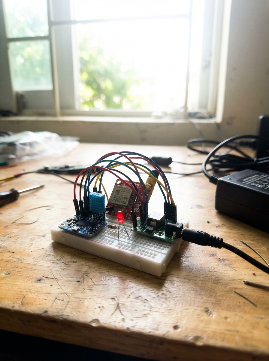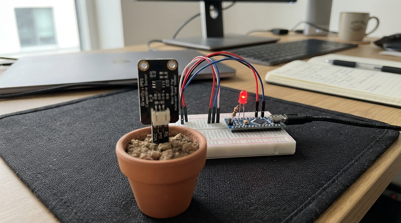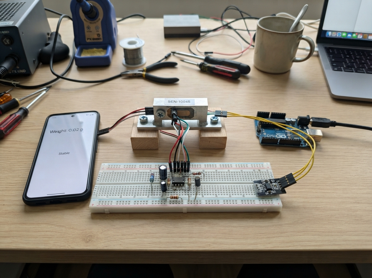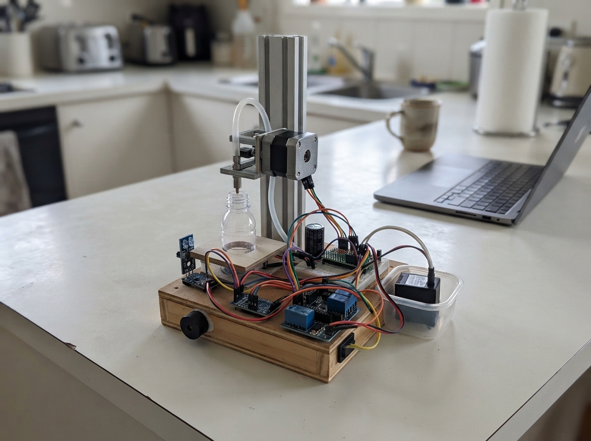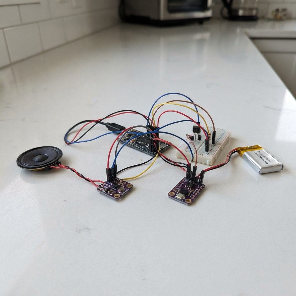
This smart sleep alarm mask uses ambient light sensing to detect when morning arrives and gently wakes the user with gradually increasing light and vibration. Built around an Arduino Uno, the mask combines a proximity sensor and ambient light sensor to monitor sleep conditions, triggering a red LED that brightens over time while a coin motor provides gentle haptic feedback.
This guide provides a complete parts list, wiring diagram, and step-by-step assembly instructions for building the prototype on a breadboard. Firmware code handles sensor input and output control, with detailed comments explaining how the light and vibration outputs are managed to create a natural wake experience.
Wiring diagram
Gather all the parts
Assemble it in 6 steps
1. Keep this prototype on the bench
Do not wear or charge the assembled mask until firmware and current measurements have been validated. The current firmware is bring-up only.
- Never charge while wearing. This is not a fire safety device.
2. Connect the two light sensors
Connect both sensors to 3.3 V and ground. Connect SDA to D4 for data and SCL to D5 for the clock. Put the proximity board inside the cup and the ambient-light board facing the room.
3. Assemble the limited-current lights
Each LED has its own 2.2 kohm resistor from 3.3 V to its anode. Connect its cathode to its color MOSFET drain. Connect MOSFET sources to ground, gates through 100 ohms to D0 for red or D1 for amber, and each gate through 100 kohms to ground.
4. Connect the motor driver
Connect 3.3 V through the 10 ohm resistor to motor positive. Connect motor negative to the MOSFET drain and source to ground. D2 drives the gate through 100 ohms, with 100 kohms from gate to ground. Connect the diode stripe to motor positive and its other end to motor negative. Verify regulator headroom and motor starting before use.
5. Connect mono speakers in series
Connect amplifier OUT+ to speaker 1 positive, speaker 1 negative to speaker 2 positive, and speaker 2 negative to OUT-. Neither output goes to ground. Connect BCLK to D8, LRC to D9, DIN to D10 and shutdown to D7. Connect VIN to battery positive and GND to common ground. Put the capacitor across this supply with correct polarity.
- Test away from ears at minimum volume first.
6. Connect button and battery last
Connect the button between D3 and ground. Check all wiring for shorts. Connect protected battery positive to the underside BAT+ pad and negative to BAT-. Insulate all joints and provide strain relief.
- Never solder directly to a pouch cell. Do not compress or puncture it.
Review all connections
1. Connections between "prox" and "Arduino"
2. Connections between "lux" and "Arduino"
3. Connections between "amp" and "Arduino"
4. Connections between "spk1" and "Arduino"
5. Connections between "spk2" and "Arduino"
6. Connections between "battery" and "Arduino"
7. Connections between "redg" and "Arduino"
8. Connections between "redpd" and "Arduino"
9. Connections between "redq" and "Arduino"
10. Connections between "red0r" and "Arduino"
11. Connections between "red0" and "Arduino"
12. Connections between "red1r" and "Arduino"
13. Connections between "red1" and "Arduino"
14. Connections between "amberg" and "Arduino"
15. Connections between "amberpd" and "Arduino"
16. Connections between "amberq" and "Arduino"
17. Connections between "amber0r" and "Arduino"
18. Connections between "amber0" and "Arduino"
19. Connections between "amber1r" and "Arduino"
20. Connections between "amber1" and "Arduino"
21. Connections between "mg" and "Arduino"
22. Connections between "mpd" and "Arduino"
23. Connections between "mq" and "Arduino"
24. Connections between "mr" and "Arduino"
25. Connections between "motor" and "Arduino"
26. Connections between "diode" and "Arduino"
27. Connections between "button" and "Arduino"
28. Connections between "cap" and "Arduino"
Deploy the firmware
#include <Arduino.h>
// Bring-up only: outputs remain off until the full application is validated.
void setup() {
  for (int p : {0,1,2,7}) { pinMode(p, OUTPUT); digitalWrite(p, LOW); }
  pinMode(3, INPUT_PULLUP);
}
void loop() { delay(100); }
Remix this project
Make it yours in one click
Open a full copy of this project in your own Schematik workspace, diagram, code, parts, and assembly steps included. Swap the sensor, add features, or redesign the whole thing with AI. The author's original stays untouched.