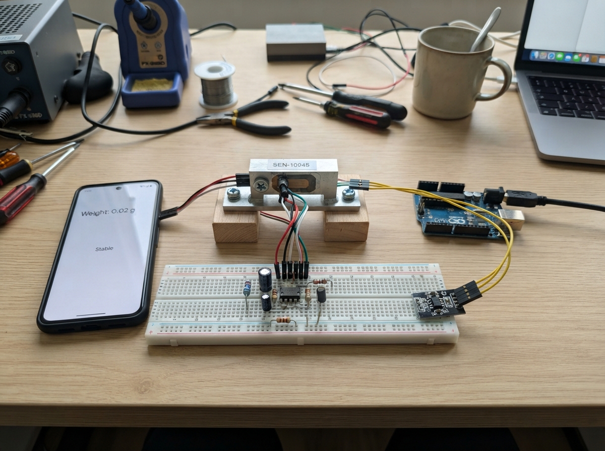
This guide builds a digital weight scale using a load cell and Arduino. The load cell's small analog signal is amplified through two stages of LM358 operational amplifiers—first a gain stage and then a subtractor stage—to produce a clean signal that the Arduino can read and convert to weight measurements.
Following this guide, makers will receive a complete wiring diagram, a parts list with recommended suppliers, Arduino firmware with tare and calibration functions, and step-by-step assembly instructions. The finished scale can measure weight by taking a tare reading, then comparing loaded readings against a known mass for accurate calibration.
Wiring diagram
Gather all the parts
Assemble it in 7 steps
1. Place the two LM358 chips
With USB unplugged, push lm358_1 and lm358_2 across the centre gap of the breadboard, each with its small notch facing the same way. The notch marks the pin-1 end, so you can count the legs correctly.
- Use two bare LM358 DIP-8 chips, not amplifier modules with extra parts already connected.
- Putting a chip in backwards swaps its power connections and can damage it when USB is plugged in.
2. Power the amplifier chips
Connect pin 8 of lm358_1 and lm358_2 to Uno 5V (power), and connect pin 4 of both chips to Uno GND (ground). Connect the positive, longer lead of c_decouple_1 to 5V and its striped negative lead to GND close to lm358_1. Do the same for c_decouple_2 beside lm358_2.
- The stripe on a 10 µF electrolytic capacitor marks its negative lead.
- Do not reverse either capacitor: reversed electrolytic capacitors can heat up and fail. Do not connect Uno 5V to LM358 pin 4; pin 4 is ground.
3. Connect the load-cell power wires
Connect load_cell_1 E+ to Uno 5V (power) and E- to Uno GND (ground). On many load cells these are red and black, but follow the E+ and E- labels or the seller's sheet rather than wire colour alone.
- Use the same 5V and GND rails used by the LM358 chips so every part shares one ground connection.
- Connecting an A+ or A- signal wire to 5V gives incorrect readings and can damage the measurement circuit.
4. Build the first amplifier stage
Connect load_cell_1 A- to lm358_1 pin 3 (signal) and A+ to lm358_1 pin 5 (signal). Fit r_gain_a, a 10 kΩ resistor, from pin 1 to pin 2, and r_gain_b, another 10 kΩ resistor, from pin 7 to pin 6. Fit r_gain_link, the 100 Ω resistor, between pins 2 and 6. Resistors have no direction.
- The two 10 kΩ resistors should be the same tolerance, preferably 1%, for stable measurements.
- Do not join A+ and A- together; they are the two separate measurement wires from the load cell.
5. Build the subtractor stage
Use four 10 kΩ resistors: connect r_diff_in_minus from lm358_1 pin 1 to lm358_2 pin 2; r_diff_fb from lm358_2 pin 1 back to pin 2; r_diff_in_plus from lm358_1 pin 7 to lm358_2 pin 3; and r_diff_ref from lm358_2 pin 3 to GND. This stage keeps the small difference caused by weight.
- Keep all four 10 kΩ resistors the same type and tolerance; matched values give the least drift.
- A loose connection in this stage can make the output stick near 0 V or 5 V.
6. Send the weight signal to the Uno
Connect lm358_2 pin 1 through r_adc_filter, the 100 Ω resistor, to Uno A0 (signal). Tie lm358_2 pins 5 and 6 to GND (ground) and leave pin 7 unconnected.
- A0 is the Arduino pin that reads the changing voltage from the load cell.
- Connect this wire to A0 only, never directly to 5V; 5V would prevent the Uno from measuring the changing signal.
7. Mount the load cell safely
Bolt one end of load_cell_1 firmly to a rigid base and bolt the load platform to the other end using its mounting holes. The metal bar must be free to bend in the direction marked by its maker.
- Keep the thin load-cell cable away from moving metal and USB cables.
- Do not exceed the 5 kg rating or clamp both ends so the bar cannot bend; either mistake can permanently damage the sensor.
Review all connections
1. Connections between "load_cell_1" and "Arduino"
2. Connections between "lm358_1" and "Arduino"
3. Connections between "r_gain_a" and "Arduino"
4. Connections between "r_gain_b" and "Arduino"
5. Connections between "r_gain_link" and "Arduino"
6. Connections between "r_diff_in_minus" and "Arduino"
7. Connections between "r_diff_fb" and "Arduino"
8. Connections between "r_diff_in_plus" and "Arduino"
9. Connections between "r_diff_ref" and "Arduino"
10. Connections between "lm358_2" and "Arduino"
11. Connections between "r_adc_filter" and "Arduino"
12. Connections between "c_decouple_1" and "Arduino"
13. Connections between "c_decouple_2" and "Arduino"
Deploy the firmware
#include <Arduino.h>

const uint8_t LOAD_CELL_PIN = A0;
const uint8_t SAMPLE_COUNT = 64;

long tareCounts = 0;
float countsPerGram = 0.086f;  // Rough starting value; calibrate with a known mass after wiring the ~x201 LM358 circuit.
unsigned long lastReportMs = 0;

long readAveragedCounts() {
  long total = 0;
  for (uint8_t i = 0; i < SAMPLE_COUNT; ++i) {
    total += analogRead(LOAD_CELL_PIN);
  }
  return total / SAMPLE_COUNT;
}

void takeTare() {
  tareCounts = readAveragedCounts();
  Serial.print(F("Tare stored at ADC count: "));
  Serial.println(tareCounts);
}

void calibrateWithKnownMass() {
  float knownGrams = Serial.parseFloat();
  if (knownGrams <= 0.0f) {
    Serial.println(F("Calibration cancelled. Send c followed by a mass in grams, for example: c 1000"));
    return;
  }

  long loadedCounts = readAveragedCounts();
  float difference = (float)(loadedCounts - tareCounts);
  if (difference == 0.0f) {
    Serial.println(F("Calibration cancelled: the reading did not change. Check the load cell and try again."));
    return;
  }

  countsPerGram = difference / knownGrams;
  Serial.print(F("Calibration saved for this power session: "));
  Serial.print(countsPerGram, 5);
  Serial.println(F(" ADC counts per gram."));
}

void handleSerialCommand() {
  if (!Serial.available()) {
    return;
  }

  char command = (char)Serial.read();
  if (command == 't' || command == 'T') {
    takeTare();
  } else if (command == 'c' || command == 'C') {
    calibrateWithKnownMass();
  }
}

void setup() {
  Serial.begin(115200);
  analogReference(DEFAULT);  // Uses the Uno's 5 V supply, the same supply used by the bridge.
  delay(500);
  takeTare();
  Serial.println(F("Load-cell scale ready."));
  Serial.println(F("Leave the platform empty for tare (t)."));
  Serial.println(F("For calibration, place a known mass on it and send c followed by grams, for example c 1000."));
}

void loop() {
  handleSerialCommand();

  unsigned long now = millis();
  if (now - lastReportMs >= 250) {
    lastReportMs = now;
    long rawCounts = readAveragedCounts();
    float grams = (rawCounts - tareCounts) / countsPerGram;

    Serial.print(F("Weight: "));
    Serial.print(grams, 1);
    Serial.print(F(" g | ADC: "));
    Serial.println(rawCounts);
  }

  delay(20);
}
Remix this project
Make it yours in one click
Open a full copy of this project in your own Schematik workspace, diagram, code, parts, and assembly steps included. Swap the sensor, add features, or redesign the whole thing with AI. The author's original stays untouched.