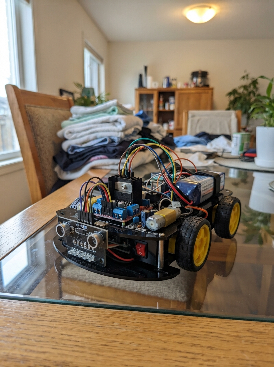
This line-following robot uses an Arduino Uno to autonomously navigate a black line on a white surface using an eight-channel infrared sensor array and proportional-derivative (PD) control. The robot is powered by a 3S lithium-ion battery and driven by two N20 micro metal gear motors controlled through an L298N motor driver module.
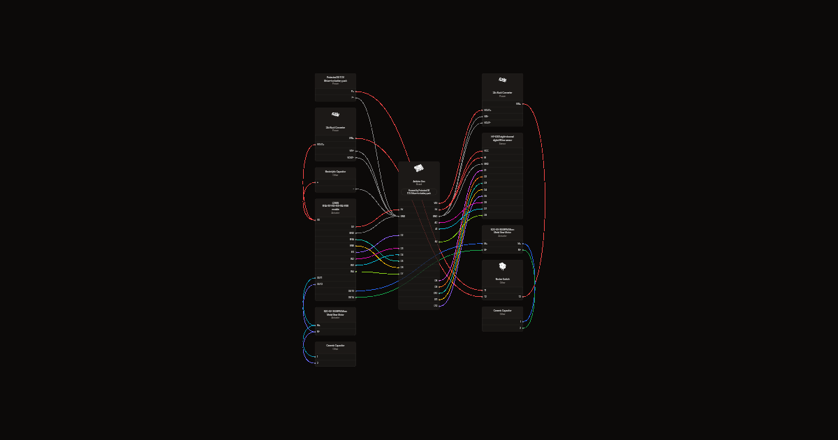
This guide provides a complete parts list, wiring diagram showing all sensor and motor connections, power distribution with the buck converter for noise suppression, and step-by-step assembly instructions. The included Arduino firmware handles sensor calibration, line detection across eight channels, motor speed control with PD feedback, and serial commands to start, stop, and test the robot's operation.
Wiring diagram
Gather all the parts
Assemble it in 6 steps
1. Mount the motors and sensor
Fit two 6V N20 motors with wheels to a chassis and add a support caster. Mount the array ahead of the wheels, initially 3mm above a white surface. D1 must be at the left and D8 at the right when looking forward from behind the robot.
- This design assumes 6V N20 motors. Do not use it unchanged for 3V motors.
2. Prepare safe battery power
Use a professionally assembled protected 3S pack, three matched 3.7V cells in series. With downstream electronics disconnected, wire the pack positive through the switch to both buck inputs. Connect pack negative to both input negatives. Measure and adjust motorbuck to 6.0V and logicbuck to 7.5V before connecting their outputs.
- Never connect loose unprotected lithium cells or solder directly to cells. Use the matching 3S charger off the robot. The pack reaches 12.6V fully charged. Buck modules are not chargers. Verify combined motor stall current stays below the converter's real continuous rating; stop if it overheats.
3. Connect the motor driver
Remove all three jumpers ENA, ENB and 5V-EN. Motorbuck positive goes to VS (often marked +12V), not to the 5V terminal. Logicbuck positive goes to Uno VIN. Uno 5V supplies driver 5V logic and the sensor. Join all grounds. ENA to D5 and ENB to D6 control speed; IN1 to D2, IN2 to D3, IN3 to D4 and IN4 to D7 control direction. OUT1/OUT2 go to the left motor; OUT3/OUT4 to the right motor.
- Do not connect the 12.6V battery directly to the chosen 6V motors. Keep motor-current wiring off solderless breadboards. The L298N loses voltage and gets hot
- so these motors may run slower than expected.
4. Suppress motor noise
Fit a 100nF ceramic capacitor across each motor's two terminals. Fit the 470uF capacitor between driver VS and GND, positive to VS and striped negative to GND.
- Reversing the electrolytic capacitor can make it burst.
5. Connect the eight sensor signals
VCC and IR go to Uno 5V for power and emitter enable; GND goes to common ground. D1 through D8 go respectively to Uno D8, D9, D10, D11, D12, A0, A1 and A2. The A pins are used as ordinary digital inputs. If your array has no IR pin, omit that wire; unused analog outputs remain disconnected.
6. Check before running
Keep wheels lifted. On reset keep all eight sensors over white for the first four seconds to learn the background. Then put the center sensors over a black line. Adjust any sensitivity controls so each channel changes between black and white. The serial controls are g to run, s to stop, c to relearn white and t to print the eight line detections. If a motor spins backward, switch off and swap just that motor's two wires. Test slowly on the floor after checking both wheels turn forward.
- The firmware stops after losing the line for half a second. At a crossing it continues straight. Battery capacity and runtime are planning estimates for a 2000mAh pack
- not measurements.
Review all connections
1. Connections between "battery" and "Arduino"
2. Connections between "switch" and "Arduino"
3. Connections between "motorbuck" and "Arduino"
4. Connections between "logicbuck" and "Arduino"
5. Connections between "driver" and "Arduino"
6. Connections between "sensor" and "Arduino"
7. Connections between "cleft" and "Arduino"
8. Connections between "cright" and "Arduino"
9. Connections between "bulk" and "Arduino"
Deploy the firmware
#include <Arduino.h>
const uint8_t sensors[8]={8,9,10,11,12,A0,A1,A2};
const uint8_t ENA=5, ENB=6, IN1=2, IN2=3, IN3=4, IN4=7;
const int BASE_SPEED=145, MAX_SPEED=220;
const float KP=0.055f, KD=0.10f;
bool white[8], running=false;
int previous=0;
unsigned long lastSeen=0,lastTick=0;
void motors(int l,int r){
  l=constrain(l,0,MAX_SPEED); r=constrain(r,0,MAX_SPEED);
  digitalWrite(IN1,l>0);digitalWrite(IN2,LOW);
  digitalWrite(IN3,r>0);digitalWrite(IN4,LOW);
  analogWrite(ENA,l);analogWrite(ENB,r);
}
void calibrate(){
  motors(0,0); running=false;
  Serial.println(F("Put ALL sensors on white background. Sampling in 3 seconds."));
  delay(3000);
  int counts[8]={0};
  for(int n=0;n<100;n++){for(int i=0;i<8;i++)counts[i]+=digitalRead(sensors[i])==HIGH;delay(5);}
  for(int i=0;i<8;i++)white[i]=counts[i]>=50;
  Serial.println(F("Calibrated. Put center sensors over black line. Send g to go, s to stop, c to recalibrate, t to test."));
}
void setup(){
  const uint8_t outputs[]={ENA,ENB,IN1,IN2,IN3,IN4};
  for(uint8_t p: outputs){digitalWrite(p,LOW);pinMode(p,OUTPUT);}
  for(uint8_t p:sensors)pinMode(p,INPUT_PULLUP);
  Serial.begin(115200);calibrate();
}
void loop(){
  while(Serial.available()){
    char c=Serial.read();
    if(c=='s'){running=false;motors(0,0);}
    if(c=='c')calibrate();
    if(c=='g'){running=true;previous=0;lastSeen=millis();}
    if(c=='t'){for(int i=0;i<8;i++)Serial.print(digitalRead(sensors[i])!=white[i]?'1':'0');Serial.println();}
  }
  unsigned long now=millis();if(now-lastTick<10)return;lastTick=now;
  if(!running)return;
  int count=0;long sum=0;
  for(int i=0;i<8;i++)if(digitalRead(sensors[i])!=white[i]){count++;sum+=(i*1000-3500);}
  if(!count){
    if(now-lastSeen>500){running=false;motors(0,0);Serial.println(F("Line lost: stopped. Reposition and send g."));}
    else if(previous<0)motors(0,110);else if(previous>0)motors(110,0);else motors(0,0);
    return;
  }
  lastSeen=now;
  if(count==8){motors(BASE_SPEED,BASE_SPEED);previous=0;return;}
  int error=sum/count;
  int correction=KP*error+KD*(error-previous);previous=error;
  motors(BASE_SPEED+correction,BASE_SPEED-correction);
}
Remix this project
Make it yours in one click
Open a full copy of this project in your own Schematik workspace, diagram, code, parts, and assembly steps included. Swap the sensor, add features, or redesign the whole thing with AI. The author's original stays untouched.