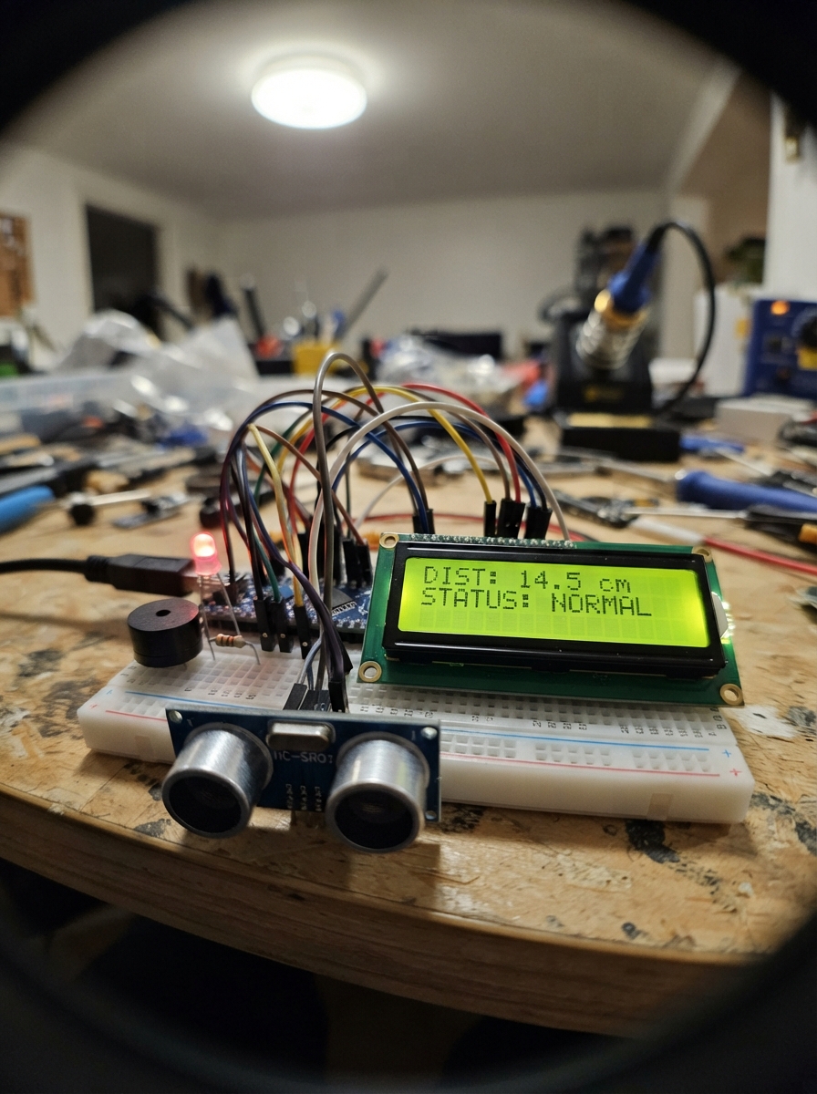
This project builds a distance monitoring system that alerts users when objects approach too closely. The HC-SR04 ultrasonic sensor continuously measures distance, while three LEDs and a piezo buzzer provide visual and audio feedback at different proximity thresholds. An I2C LCD display shows real-time distance readings.
The guide includes a complete wiring diagram, parts list with recommended suppliers, and ready-to-upload Arduino firmware. Assembly takes about 30 minutes and requires only basic soldering skills. Makers will learn how to interface multiple sensors and outputs with an Arduino, implement state-based alerting logic, and use I2C communication for the LCD display.
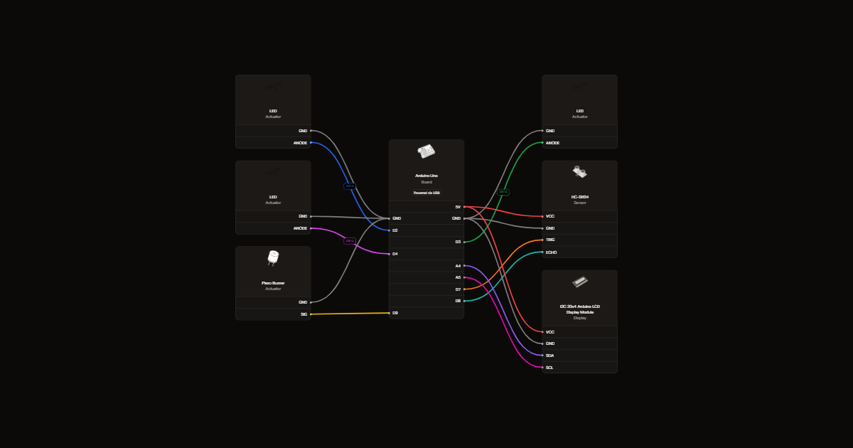
Wiring diagram
Gather all the parts
Assemble it in 5 steps
1. Disconnect power before wiring
Unplug USB. Use jumper wires and a breadboard if available. All GND connections must share Arduino GND. Power this project from USB.
2. Connect the three LEDs
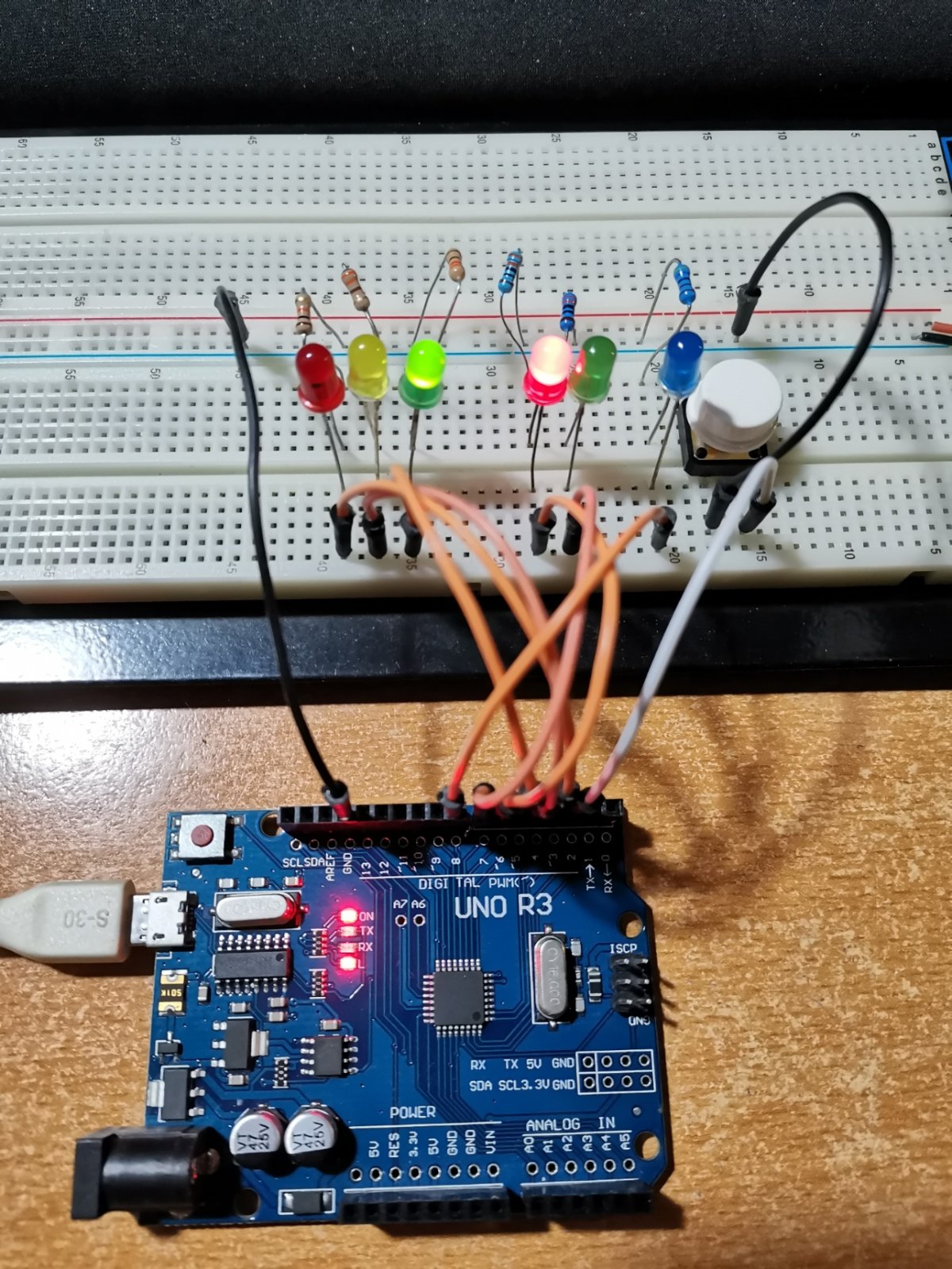
D2 goes through r_red (220 ohms) to the red LED long leg. D3 goes through r_yellow (220 ohms) to the yellow or green LED long leg. D4 goes through r_blue (220 ohms) to the blue or white LED long leg. Connect each short leg (flat-edge side) to GND. Resistors work either way round.
- Never connect an LED directly to an Arduino output without its series resistor.
3. Connect the ultrasonic sensor
Connect HC-SR04 VCC to 5V, GND to GND, TRIG to D7 (trigger), and ECHO to D8 (return pulse). Follow the printed pin labels. Point both round transducers at the object.
- Use a flat target at least 2 cm away; soft or angled objects can give unreliable readings.
4. Connect the passive piezo buzzer
Connect the piezo signal lead to D9 and its other lead to GND. If marked, use + for D9 and - for GND.
- This circuit uses a small passive piezo, not a high-current magnetic buzzer or loudspeaker.
5. Connect the four-line LCD
Connect LCD VCC to 5V, GND to GND, SDA to A4 (data), and SCL to A5 (clock). The code automatically detects a compatible PCF8574 or MCP23008 backpack. Turn its contrast screw gently if the backlight is on but the text is invisible.
- Check VCC and GND carefully before reconnecting USB; swapped power can damage the display.
Review all connections
1. Connections between "r_red" and "Arduino"
2. Connections between "red" and "Arduino"
3. Connections between "r_yellow" and "Arduino"
4. Connections between "yellow" and "Arduino"
5. Connections between "r_blue" and "Arduino"
6. Connections between "blue" and "Arduino"
7. Connections between "sonar" and "Arduino"
8. Connections between "buzzer" and "Arduino"
9. Connections between "lcd" and "Arduino"
Deploy the firmware
#include <Arduino.h>
#include <Wire.h>
#include <hd44780.h>
#include <hd44780ioClass/hd44780_I2Cexp.h>

constexpr uint8_t RED=2, YELLOW=3, BLUE=4, TRIG=7, ECHO=8, BUZZER=9;
hd44780_I2Cexp lcd;
bool lcdReady=false;
char previous[4][21] = {};
int previousState=-1;
unsigned long lastSample=0;

void writeRow(uint8_t row, const char *text) {
  char padded[21];
  memset(padded, ' ', 20);
  padded[20]='\0';
  size_t count=strlen(text);
  if(count>20) count=20;
  memcpy(padded,text,count);
  if(lcdReady && strcmp(previous[row],padded)!=0) {
    lcd.setCursor(0,row);
    lcd.print(padded);
    strcpy(previous[row],padded);
  }
}
void setup() {
  Serial.begin(9600);
  pinMode(RED,OUTPUT); pinMode(YELLOW,OUTPUT); pinMode(BLUE,OUTPUT);
  pinMode(BUZZER,OUTPUT); pinMode(TRIG,OUTPUT); pinMode(ECHO,INPUT);
  digitalWrite(TRIG,LOW);
  noTone(BUZZER);
  Wire.begin();
  lcdReady=(lcd.begin(20,4)==0); // Detect backpack address and pin mapping.
  if(!lcdReady) Serial.println(F("LCD init failed; check wires and contrast."));
  writeRow(0,"Distance monitor");
}
void loop() {
  if(millis()-lastSample<200) return;
  lastSample=millis();
  digitalWrite(TRIG,LOW); delayMicroseconds(2);
  digitalWrite(TRIG,HIGH); delayMicroseconds(10); digitalWrite(TRIG,LOW);
  unsigned long duration=pulseIn(ECHO,HIGH,30000UL);
  float cm=duration/58.0f;
  bool valid=duration!=0 && cm>=2.0f && cm<=400.0f;
  // States: 0 invalid, 1 far, 2 close, 3 closer, 4 unspecified gap.
  int state=0;
  if(valid) {
    if(cm>=20.0f) state=1;
    else if(cm<=10.0f) state=2;
    else if(cm<=15.0f) state=3;
    else state=4;
  }
  if(state!=previousState) {
    digitalWrite(RED,state==1);
    digitalWrite(BLUE,state==2);
    digitalWrite(YELLOW,state==3);
    if(state==2) tone(BUZZER,4000);
    else noTone(BUZZER);
    previousState=state;
  }
  char line[21];
  if(valid) {
    char number[12]; dtostrf(cm,5,1,number);
    snprintf(line,sizeof(line),"Distance: %s cm",number);
  } else strcpy(line,"Distance: no reading");
  writeRow(1,line);
  switch(state) {
    case 1: writeRow(2,"The Distance is far"); writeRow(3,""); break;
    case 2: writeRow(2,"The OBJECT is"); writeRow(3,"TOO CLOSE"); break;
    case 3: writeRow(2,"Object is Closer"); writeRow(3,""); break;
    case 4: writeRow(2,"Object is between"); writeRow(3,"15 and 20 cm"); break;
    default: writeRow(2,"Check sensor/target"); writeRow(3,"Outputs OFF"); break;
  }
  Serial.println(line);
}
Remix this project
Make it yours in one click
Open a full copy of this project in your own Schematik workspace, diagram, code, parts, and assembly steps included. Swap the sensor, add features, or redesign the whole thing with AI. The author's original stays untouched.