Community project
Arduino Multi-Sensor Control System
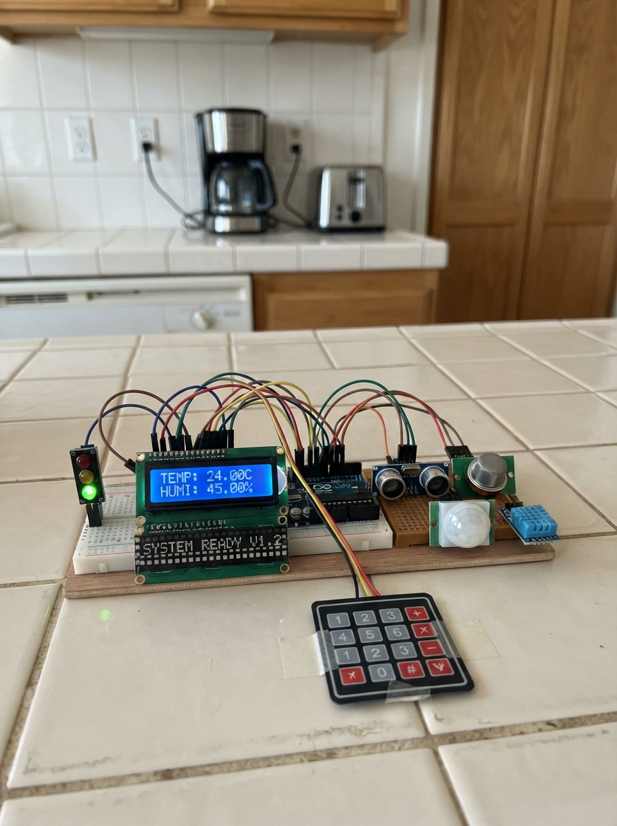
This Arduino multi-sensor control system integrates distance sensing, motion detection, gas monitoring, temperature and humidity measurement, and line tracking into a single unified platform. The project combines an LCD display, LED matrix, traffic light indicators, and a 4x4 keypad interface to create an interactive monitoring and control station capable of driving motors, servos, and relay outputs.
The guide provides a complete wiring diagram showing all sensor and actuator connections, a full parts list with pinout references, and step-by-step assembly instructions organized by functional sections. Readers will receive tested firmware code, calibration procedures for each sensor module, and verification steps to ensure proper operation before final enclosure assembly.
Wiring diagram
Gather all the parts
Assemble it in 8 steps
1. Build the protected power section
Mount the battery holder, 2S charger, 5V buck converter, and 3.3V regulator at one edge of a perfboard or PCB. Use screw terminals for battery and charger wires. Wire battery BAT+ to charger BAT+ and BAT- to charger BAT-. Wire charger OUT+ to buck VIN+ and OUT- to buck VIN-. Adjust the buck converter to exactly 5.0V before connecting the rest of the circuit. Route a thick 5V track or red wire bus and a thick GND track or black wire bus across the board. Feed the Mega from the regulated 5V rail through its 5V pin and GND through a Mega GND pin. Wire the AMS1117 VIN to 5V, GND to GND, and VOUT to a separate 3.3V rail for the ESP-01 (power).
- Use a 5V buck converter rated for at least 3A because motors, relays, displays, and sensors can draw more current together than the Mega can supply.
- Fit a 470µF or larger electrolytic capacitor across 5V and GND beside the motor and relay connectors; its marked negative stripe goes to GND.
- Never connect the 7.4–8.4V battery rail directly to the Mega 5V pin, displays, sensors, ESP-01, servo, or stepper driver — it can damage them.
- Do not rely on thin signal wire for the 5V motor and relay supply; thin wire can heat up and cause resets.
2. Mount the Mega and install service connectors
Bolt the Mega 2560 to the enclosure or main PCB using standoffs. Do not solder wires directly to the Mega: use stackable headers or locking plug connectors so the board can be removed. Put labelled 3-pin headers beside each sensor connection in the order 5V, GND, SIGNAL. Put labelled screw terminals for the battery, charger input, DC motors, and relay contact loads. Join every module ground to the one GND bus (ground).
- Label every connector with the signal name and Mega pin number before soldering.
- Keep the battery, motor, and relay-contact wiring along one side of the board; keep displays and analog sensors on the opposite side.
3. Wire the screens and keypad panel
Use panel cut-outs for the LCD, OLED, MAX7219 displays, traffic-light LEDs, and 4x4 keypad. LCD: VCC → 5V (power), GND → GND (ground), SDA → Mega D20 (data), SCL → Mega D21 (clock). OLED: VCC → 5V (power), GND → GND (ground), SDA → D20 (data), SCL → D21 (clock); use a module marked 3.3–5V or 5V-compatible. Both MAX7219 modules: VCC → 5V (power), GND → GND (ground), DIN → D51 (data), CLK → D52 (clock). Connect 6-digit CS → A2/D56 (select) and 8x8 CS → A3/D57 (select). Keypad R1/R2/R3/R4 → D25/D26/D27/D28 (row signals); C1/C2/C3/C4 → D29/D30/D31/A4/D58 (column signals). Traffic-light RED/YELLOW/GREEN → D22/D23/D24 (signals), traffic-light GND → GND (ground).
- Do not use a 3.3V-only OLED on this shared LCD bus; its signal pull-up resistors can be exposed to 5V and be damaged.
- Keep D20 and D21 as a short twisted pair or adjacent PCB tracks because both screens use them.
4. Wire the sensor headers
HC-SR04: VCC → 5V (power), GND → GND (ground), TRIG → A5/D59 (signal), ECHO → A6/D60 (signal). PIR: VCC → 5V (power), GND → GND (ground), OUT → A7/D61 (signal). MQ-2: VCC → 5V (power), GND → GND (ground), AO → A0/D54 (signal). DHT11: VCC → 5V (power), GND → GND (ground), DATA → A9/D63 (signal). IR module: VCC → 5V (power), GND → GND (ground), AO → A1/D55 (signal). Capacitive soil probe: red/VCC → 5V (power), black/GND → GND (ground), yellow/AOUT → A8/D62 (signal). SW-420 vibration module: VCC → 5V (power), GND → GND (ground), DO → D2 (signal). Flex sensor: one end → 5V (power); the other end joins A14/D68 and one end of the 10kΩ resistor (signal); the other resistor end → GND (ground).
- Use a detachable 3-wire cable for the soil probe and vibration module so the enclosure can be opened.
- Mount the flex sensor where it can bend freely; repeated hard creases can break it.
- Keep the MQ-2 away from the OLED, LCD, and plastic enclosure wall because its sensing head becomes hot.
- Do not install the soil probe in wet soil while the board is unpowered only if its cable might pull on the connector; support the cable so the connector is not stressed.
5. Wire buttons and indicator LEDs
Mount the three tactile push buttons on the front panel. Button 1: one terminal → D10 (signal), opposite terminal → GND (ground). Button 2: one terminal → D11 (signal), opposite terminal → GND (ground). Button 3: one terminal → D12 (signal), opposite terminal → GND (ground). For the discrete LEDs, D7 → 220Ω resistor → red LED long leg/anode (signal); red LED short leg/cathode → GND. D8 → 220Ω → yellow LED long leg (signal); yellow LED short leg → GND. D9 → 220Ω → green LED long leg (signal); green LED short leg → GND.
- Each LED needs its own 220Ω resistor. Connecting an LED directly to a Mega pin can damage the LED and the Mega output.
- On four-leg tactile switches, use terminals from opposite sides of the switch, not two terminals on the same side.
6. Wire motors and relay output section
SG90: red → external 5V bus (power), brown/black → GND (ground), orange/yellow → D5 (signal). ULN2003: VCC → 5V (power), GND → GND (ground), IN1/IN2/IN3/IN4 → A10/D64, A11/D65, A12/D66, A13/D67 (signals); plug the 28BYJ-48 into its matching driver socket. L298N: VS → charger OUT+ battery rail (motor power), GND → common GND (ground), 5V → 5V bus (logic power), ENA → D6 (speed signal), IN1/IN2/IN3/IN4 → A15/D69, D44, D45, D46 (direction signals); motor 1 → OUT1/OUT2 and motor 2 → OUT3/OUT4. Original single relay: VCC → 5V (power), GND → GND (ground), IN → D3 (signal). Four-relay module: VCC → 5V (power), GND → GND (ground), IN1 → D13, IN2 → D14, IN3 → D15, IN4 → D16 (signals).
- Use relay COM and NO terminals only for low-voltage loads unless a qualified person designs the mains wiring, fuse, enclosure, and safety clearances.
- Do not power the servo, ULN2003, L298N, or relay coils from the Mega's 5V pin; connect them to the external regulated 5V bus.
- Keep motor wires physically away from the DHT11, flex sensor, soil sensor, and I²C tracks to reduce electrical noise.
7. Wire the ESP-01 safely
ESP-01 VCC → 3.3V (power), GND → GND (ground), EN → 3.3V (enable), RST → 3.3V (normal running), GPIO0 → 3.3V (normal running), GPIO2 → 3.3V (normal running), TX → Mega D19/RX1 (data). Make the RX divider: Mega D18/TX1 → 1kΩ resistor → junction; junction → ESP-01 RX (data) and junction → 2kΩ resistor → GND (ground).
- Never connect Mega D18 directly to ESP-01 RX; 5V logic can damage the Wi-Fi module.
- Use a 3.3V regulator that can supply at least 500mA peak, and add a 100µF capacitor between ESP-01 3.3V and GND close to the module; weak 3.3V power causes Wi-Fi resets.
8. Test each section before closing the enclosure
With motors and relay loads disconnected, power the board and measure 5V at each 5V header and 3.3V at the ESP-01 header. Then connect one section at a time: displays, keypad/buttons, sensors, relays, and finally motors. Verify every plug matches its printed label before fitting the enclosure lid. The firmware uses keypad 1, 2, 3, and 4 to toggle four relay channels; A and B turn the stepper one way or the other; C toggles the DC motor; * and D move the servo; # toggles the original relay.
- Use heat-shrink sleeve on soldered wire joints and cable ties for strain relief.
- Use a multimeter continuity check to find accidental shorts between 5V and GND before inserting the battery.
- Disconnect the battery before changing any wiring.
- A reversed power connector can damage multiple modules at once; check 5V and GND with a meter before plugging each module in.
Review all connections
1. Connections between "battery_pack" and "Arduino"
2. Connections between "charger_2s" and "Arduino"
3. Connections between "buck_5v" and "Arduino"
4. Connections between "regulator_3v3" and "Arduino"
5. Connections between "lcd_16x2" and "Arduino"
6. Connections between "seven_segment_max7219" and "Arduino"
7. Connections between "dot_matrix_max7219" and "Arduino"
8. Connections between "traffic_light" and "Arduino"
9. Connections between "keypad_4x4" and "Arduino"
10. Connections between "hcsr04" and "Arduino"
11. Connections between "pir" and "Arduino"
12. Connections between "mq2" and "Arduino"
13. Connections between "dht11" and "Arduino"
14. Connections between "ir_sensor" and "Arduino"
15. Connections between "servo" and "Arduino"
16. Connections between "uln2003_stepper" and "Arduino"
17. Connections between "l298n" and "Arduino"
18. Connections between "esp01" and "Arduino"
19. Connections between "divider_1k" and "Arduino"
20. Connections between "divider_2k" and "Arduino"
21. Connections between "relay" and "Arduino"
22. Connections between "resistor_led_1" and "Arduino"
23. Connections between "status_led_1" and "Arduino"
24. Connections between "resistor_led_2" and "Arduino"
25. Connections between "status_led_2" and "Arduino"
26. Connections between "resistor_led_3" and "Arduino"
27. Connections between "status_led_3" and "Arduino"
28. Connections between "button_1" and "Arduino"
29. Connections between "button_2" and "Arduino"
30. Connections between "button_3" and "Arduino"
31. Connections between "vibration_sensor" and "Arduino"
32. Connections between "soil_sensor" and "Arduino"
33. Connections between "oled_128x64" and "Arduino"
34. Connections between "flex_sensor" and "Arduino"
35. Connections between "flex_divider_10k" and "Arduino"
36. Connections between "relay_bank_4" and "Arduino"
Deploy the firmware
#include <Wire.h>
#include <LiquidCrystal_I2C.h>
#include <Keypad.h>
#include <DHT.h>
#include <Servo.h>
#include <AccelStepper.h>
#include <Adafruit_GFX.h>
#include <Adafruit_SSD1306.h>

#define MAX7_DIN 51
#define MAX7_CLK 52
#define MAX7_CS A2
#define MATRIX_CS A3
#define TRAFFIC_RED 22
#define TRAFFIC_YELLOW 23
#define TRAFFIC_GREEN 24
#define ULTRASONIC_TRIG A5
#define ULTRASONIC_ECHO A6
#define PIR_PIN A7
#define MQ2_ANALOG A0
#define DHT_PIN A9
#define IR_ANALOG A1
#define SERVO_PIN 5
#define STEPPER_IN1 A10
#define STEPPER_IN2 A11
#define STEPPER_IN3 A12
#define STEPPER_IN4 A13
#define MOTOR_IN1 A15
#define MOTOR_IN2 44
#define MOTOR_IN3 45
#define MOTOR_IN4 46
#define MOTOR_ENA 6
#define RELAY_PIN 3
#define STATUS_RED 7
#define STATUS_YELLOW 8
#define STATUS_GREEN 9
#define BUTTON_MODE 10
#define BUTTON_RELAY 11
#define BUTTON_SERVO 12
#define VIBRATION_PIN 2
#define SOIL_ANALOG A8
#define FLEX_ANALOG A14
#define RELAY_1_PIN 13
#define RELAY_2_PIN 14
#define RELAY_3_PIN 15
#define RELAY_4_PIN 16

LiquidCrystal_I2C lcd(0x27, 16, 2);
Adafruit_SSD1306 oled(128, 64, &Wire, -1);
DHT dht(DHT_PIN, DHT11);
Servo trainerServo;
AccelStepper stepper(AccelStepper::HALF4WIRE, STEPPER_IN1, STEPPER_IN3, STEPPER_IN2, STEPPER_IN4);

const byte ROWS = 4, COLS = 4;
char keys[ROWS][COLS] = {{'1','2','3','A'}, {'4','5','6','B'}, {'7','8','9','C'}, {'*','0','#','D'}};
byte rowPins[ROWS] = {25, 26, 27, 28};
byte colPins[COLS] = {29, 30, 31, A4};
Keypad keypad = Keypad(makeKeymap(keys), rowPins, colPins, ROWS, COLS);

bool relayOn = false;
bool relayBank[4] = {false, false, false, false};
bool motorOn = false;
int servoAngle = 90;
unsigned long lastSample = 0;
unsigned long lastButton = 0;
float temperatureC = NAN, humidity = NAN;
long distanceCm = -1;
int gasValue = 0, irValue = 0, soilValue = 0, flexValue = 0;
bool motion = false, vibration = false;

void maxWrite(byte cs, byte reg, byte value) {
  digitalWrite(cs, LOW);
  shiftOut(MAX7_DIN, MAX7_CLK, MSBFIRST, reg);
  shiftOut(MAX7_DIN, MAX7_CLK, MSBFIRST, value);
  digitalWrite(cs, HIGH);
}

void initMax(byte cs) {
  maxWrite(cs, 0x0F, 0x00);
  maxWrite(cs, 0x09, 0x00);
  maxWrite(cs, 0x0A, 0x03);
  maxWrite(cs, 0x0B, 0x07);
  maxWrite(cs, 0x0C, 0x01);
  for (byte i = 1; i <= 8; i++) maxWrite(cs, i, 0);
}

void showNumber(long value) {
  bool negative = value < 0;
  unsigned long n = negative ? -value : value;
  for (byte digit = 1; digit <= 6; digit++) {
    byte segment = n % 10;
    n /= 10;
    if (digit > 1 && n == 0 && !negative) maxWrite(MAX7_CS, digit, 0x0F);
    else maxWrite(MAX7_CS, digit, segment);
  }
  if (negative) maxWrite(MAX7_CS, 6, 0x0A);
}

void drawMatrix(bool alarm) {
  const byte okIcon[8] = {0x00, 0x00, 0x00, 0x18, 0x18, 0x00, 0x00, 0x00};
  const byte alarmIcon[8] = {0x18, 0x3C, 0x7E, 0xDB, 0xFF, 0x18, 0x18, 0x00};
  for (byte row = 0; row < 8; row++) maxWrite(MATRIX_CS, row + 1, alarm ? alarmIcon[row] : okIcon[row]);
}

long readDistanceCm() {
  digitalWrite(ULTRASONIC_TRIG, LOW);
  delayMicroseconds(2);
  digitalWrite(ULTRASONIC_TRIG, HIGH);
  delayMicroseconds(10);
  digitalWrite(ULTRASONIC_TRIG, LOW);
  unsigned long duration = pulseIn(ULTRASONIC_ECHO, HIGH, 30000UL);
  if (duration == 0) return -1;
  return duration / 58L;
}

void setMotor(bool on) {
  motorOn = on;
  digitalWrite(MOTOR_IN1, on ? HIGH : LOW);
  digitalWrite(MOTOR_IN2, LOW);
  digitalWrite(MOTOR_IN3, LOW);
  digitalWrite(MOTOR_IN4, LOW);
  analogWrite(MOTOR_ENA, on ? 180 : 0);
}

void updateIndicators() {
  bool gasAlarm = gasValue > 450;
  bool proximityAlarm = distanceCm > 0 && distanceCm < 15;
  bool alarm = gasAlarm || motion || proximityAlarm;
  digitalWrite(STATUS_RED, alarm);
  digitalWrite(STATUS_YELLOW, !alarm && (irValue < 400));
  digitalWrite(STATUS_GREEN, !alarm && (irValue >= 400));
  digitalWrite(TRAFFIC_RED, alarm);
  digitalWrite(TRAFFIC_YELLOW, !alarm && (irValue < 400));
  digitalWrite(TRAFFIC_GREEN, !alarm && (irValue >= 400));
  drawMatrix(alarm);
}

void printOled() {
  oled.clearDisplay();
  oled.setTextSize(1); oled.setTextColor(SSD1306_WHITE);
  oled.setCursor(0, 0); oled.print("Mega Trainer Board");
  oled.setCursor(0, 14); oled.print("T:"); oled.print(temperatureC, 1); oled.print("C H:"); oled.print(humidity, 0); oled.print("%");
  oled.setCursor(0, 26); oled.print("Dist:"); oled.print(distanceCm); oled.print("cm Gas:"); oled.print(gasValue);
  oled.setCursor(0, 38); oled.print("Soil:"); oled.print(soilValue); oled.print(" Flex:"); oled.print(flexValue);
  oled.setCursor(0, 50); oled.print("P:"); oled.print(motion ? "ON" : "--"); oled.print(" Vib:"); oled.print(vibration ? "ON" : "--");
  oled.display();
}

void setRelayBank(byte channel, bool on) {
  relayBank[channel] = on;
  const byte relayPins[4] = {RELAY_1_PIN, RELAY_2_PIN, RELAY_3_PIN, RELAY_4_PIN};
  digitalWrite(relayPins[channel], on ? LOW : HIGH); // common relay modules are active-low
}

void printLcd() {
  lcd.setCursor(0, 0);
  lcd.print("T:");
  if (isnan(temperatureC)) lcd.print("--"); else lcd.print((int)temperatureC);
  lcd.print(" H:");
  if (isnan(humidity)) lcd.print("--"); else lcd.print((int)humidity);
  lcd.print("%   ");
  lcd.setCursor(0, 1);
  lcd.print("D:");
  if (distanceCm < 0) lcd.print("---"); else lcd.print(distanceCm);
  lcd.print(" G:");
  lcd.print(gasValue);
  lcd.print("   ");
}

bool pressed(byte pin) {
  if (digitalRead(pin) == LOW && millis() - lastButton > 180) {
    lastButton = millis();
    return true;
  }
  return false;
}

void handleControls() {
  if (pressed(BUTTON_RELAY)) {
    relayOn = !relayOn;
    digitalWrite(RELAY_PIN, relayOn ? LOW : HIGH); // common relay modules are active-low
  }
  if (pressed(BUTTON_SERVO)) {
    servoAngle = (servoAngle == 90) ? 0 : 90;
    trainerServo.write(servoAngle);
  }
  if (pressed(BUTTON_MODE)) setMotor(!motorOn);

  char key = keypad.getKey();
  if (!key) return;
  if (key == 'A') stepper.move(512);
  else if (key == 'B') stepper.move(-512);
  else if (key == 'C') setMotor(!motorOn);
  else if (key == 'D') { servoAngle = 180; trainerServo.write(servoAngle); }
  else if (key >= '1' && key <= '4') { byte channel = key - '1'; setRelayBank(channel, !relayBank[channel]); }
  else if (key == '*') { servoAngle = 0; trainerServo.write(servoAngle); }
  else if (key == '#') { relayOn = !relayOn; digitalWrite(RELAY_PIN, relayOn ? LOW : HIGH); }
}

void sampleAndReport() {
  humidity = dht.readHumidity();
  temperatureC = dht.readTemperature();
  distanceCm = readDistanceCm();
  gasValue = analogRead(MQ2_ANALOG);
  irValue = analogRead(IR_ANALOG);
  soilValue = analogRead(SOIL_ANALOG);
  flexValue = analogRead(FLEX_ANALOG);
  motion = digitalRead(PIR_PIN) == HIGH;
  vibration = digitalRead(VIBRATION_PIN) == HIGH;
  updateIndicators();
  showNumber(distanceCm < 0 ? 0 : distanceCm);
  printLcd();
  printOled();
  Serial1.print("T="); Serial1.print(temperatureC);
  Serial1.print(",H="); Serial1.print(humidity);
  Serial1.print(",D="); Serial1.print(distanceCm);
  Serial1.print(",G="); Serial1.print(gasValue);
  Serial1.print(",PIR="); Serial1.print(motion ? 1 : 0);
  Serial1.print(",IR="); Serial1.print(irValue);
  Serial1.print(",SOIL="); Serial1.print(soilValue);
  Serial1.print(",FLEX="); Serial1.print(flexValue);
  Serial1.print(",VIB="); Serial1.println(vibration ? 1 : 0);
}

void setup() {
  pinMode(MAX7_DIN, OUTPUT); pinMode(MAX7_CLK, OUTPUT);
  pinMode(MAX7_CS, OUTPUT); pinMode(MATRIX_CS, OUTPUT);
  initMax(MAX7_CS); initMax(MATRIX_CS);
  pinMode(ULTRASONIC_TRIG, OUTPUT); pinMode(ULTRASONIC_ECHO, INPUT);
  pinMode(PIR_PIN, INPUT);
  pinMode(MOTOR_IN1, OUTPUT); pinMode(MOTOR_IN2, OUTPUT); pinMode(MOTOR_IN3, OUTPUT); pinMode(MOTOR_IN4, OUTPUT); pinMode(MOTOR_ENA, OUTPUT);
  pinMode(RELAY_PIN, OUTPUT); digitalWrite(RELAY_PIN, HIGH);
  pinMode(VIBRATION_PIN, INPUT);
  pinMode(RELAY_1_PIN, OUTPUT); pinMode(RELAY_2_PIN, OUTPUT); pinMode(RELAY_3_PIN, OUTPUT); pinMode(RELAY_4_PIN, OUTPUT);
  for (byte i = 0; i < 4; i++) setRelayBank(i, false);
  pinMode(STATUS_RED, OUTPUT); pinMode(STATUS_YELLOW, OUTPUT); pinMode(STATUS_GREEN, OUTPUT);
  pinMode(TRAFFIC_RED, OUTPUT); pinMode(TRAFFIC_YELLOW, OUTPUT); pinMode(TRAFFIC_GREEN, OUTPUT);
  pinMode(BUTTON_MODE, INPUT_PULLUP); pinMode(BUTTON_RELAY, INPUT_PULLUP); pinMode(BUTTON_SERVO, INPUT_PULLUP);
  lcd.init(); lcd.backlight(); lcd.clear();
  lcd.print("Mega Trainer"); lcd.setCursor(0, 1); lcd.print("Starting...");
  if (!oled.begin(SSD1306_SWITCHCAPVCC, 0x3C)) while (true) { }
  oled.clearDisplay(); oled.setTextSize(1); oled.setTextColor(SSD1306_WHITE); oled.setCursor(0, 0); oled.print("Mega Trainer Starting"); oled.display();
  dht.begin();
  trainerServo.attach(SERVO_PIN); trainerServo.write(servoAngle);
  stepper.setMaxSpeed(500); stepper.setAcceleration(250);
  Serial.begin(115200); Serial1.begin(9600);
  setMotor(false);
  delay(1200);
}

void loop() {
  handleControls();
  stepper.run();
  if (millis() - lastSample >= 1000) {
    lastSample = millis();
    sampleAndReport();
  }
}
Remix this project
Make it yours in one click
Open a full copy of this project in your own Schematik workspace — diagram, code, parts, and assembly steps included. Swap the sensor, add features, or redesign the whole thing with AI. The author's original stays untouched.