Community project
Offline Classroom Controller
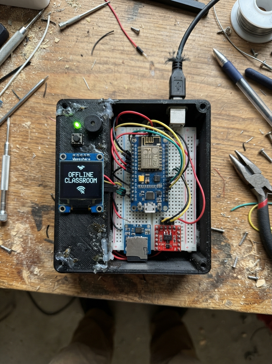
The Offline Classroom Controller is a standalone device that manages classroom sessions without requiring network connectivity. Built around an Arduino Uno and ESP8266, it features a 128×128 OLED display for real-time feedback, push buttons for navigation, status LEDs for quick visual indication, and MicroSD storage for session data. The device can generate QR codes for student check-in and track attendance throughout a session.
This guide provides a complete wiring diagram, full parts list with sourcing information, and step-by-step assembly instructions for the 3D-printed enclosure. You'll also get the complete Arduino firmware with display management, button debouncing, and session state handling, plus guidance on configuring the device for your classroom environment.
Wiring diagram

Gather all the parts
Assemble it in 7 steps
1. Prepare the printed enclosure
Print or machine the 100 mm cube as a 2.5 mm wall shell with a separate front bezel and rear plate. Make the front glass recess 82 × 82 mm with rounded corners, add a smaller 30 × 30 mm clear viewing opening centered behind it for the selected OLED, and leave at least 3 mm clearance behind every panel opening.
- Use four M2.5 brass heat-set inserts at the rear corners and four more front standoffs for the OLED board.
- The 82 mm black glass is a cosmetic front window; the prototype OLED has a 26.86 mm active square area centered within it.
- Do not make the glass opening the same size as the OLED circuit board; the board needs a covered mounting ledge and room for its connector.
2. Fit the screen and front indicators
Place the OLED board on four 6 mm plastic or brass standoffs behind the centered black front glass. Fit the green, yellow, and red LEDs in a row below the window, then put one 220 Ω resistor in series with each LED long leg before its board wire. Connect each LED short leg to the shared GND rail.
- Keep the LED leads insulated where they pass the metal-look enclosure.
- Mark the long LED leg before trimming it; it is the positive leg.
- Do not connect an LED directly to a Uno pin without its 220 Ω resistor — excess current can damage the LED or the board pin.
3. Install the controller boards
Lay the Arduino Uno R3 flat on four brass posts on the enclosure floor. Mount the NodeMCU upright behind it in two printed clips, leaving air space above both boards. Install the level-shifter board between them so its 5V side faces the Uno and its 3.3V side faces the NodeMCU.
- Keep a 5 mm gap around board edges so the rear plate and cable bundle do not press on components.
- The NodeMCU uses 3.3 V signal pins; route both serial signal paths through the level shifter, not directly from the Uno.
4. Wire the screen and storage
Connect OLED VCC → 5V (power), OLED GND → GND (ground), OLED SDA → A4 (screen data), and OLED SCL → A5 (screen clock). Connect microSD VCC → 5V (power), GND → GND (ground), MOSI → D11 (data out), MISO → D12 (data in), SCK → D13 (clock), and CS → D10 (card select).
- Use short wires for the OLED and microSD connections so the display remains stable and the side microSD slot can be reached.
- Make sure VCC and GND are not swapped — swapped power can damage the screen or card module.
5. Wire the rear controls and sounder
Fit the four nearly flush rear buttons in order Nav, Select, Back, Session. Connect each button's signal leg to D2, D3, D4, and D5 respectively, and connect the other leg of every button to GND. Put the buzzer below the top sound-hole grid and connect its signal → D9 and its other lead → GND.
- The Session button can have the cyan ring printed around its rear cutout; it is only a visual accent, not an electrical light ring.
- Turn the buzzer so its sound opening faces the top vent holes; covering it makes alerts very quiet.
6. Wire the status LEDs and NodeMCU link
Connect Uno D6 → green 220 Ω resistor → green LED long leg (ready light), D7 → yellow 220 Ω resistor → yellow LED long leg (processing light), and D8 → red 220 Ω resistor → red LED long leg (warning light). Connect all LED short legs → GND. Connect Uno A0 → level shifter HV1 and level shifter LV1 → NodeMCU RX; connect NodeMCU TX → level shifter LV2 and level shifter HV2 → Uno A1. Connect shifter HV → 5V, LV → 3.3V, and GND → GND.
- Label the two serial wires before closing the enclosure: A0 is the Uno transmit path and A1 is the Uno receive path.
- Do not join Uno A0/A1 directly to NodeMCU RX/TX — the Uno's 5V output can harm the NodeMCU input.
7. Fit ports, close the rear, and add the feet
Fit the USB-B extension, regulated 5 V barrel jack, and Micro-USB service extension in the recessed bottom rear openings. Connect their grounds to the common GND rail. Use only one power input at a time. Close the rear plate with four screws, then stick four small rubber feet under the enclosure. The optional dark graphite swivel base stays separate below the cube.
- Keep the USB-B extension routed to the Uno USB connector and the Micro-USB extension routed to the NodeMCU connector before fitting the rear plate.
- Use only a regulated 5 V barrel supply. Do not connect USB power and the barrel supply at the same time because two power sources can damage the boards.
Review all connections
1. Connections between "oled_128x128" and "Arduino"
2. Connections between "microsd" and "Arduino"
3. Connections between "buzzer" and "Arduino"
4. Connections between "nav_button" and "Arduino"
5. Connections between "select_button" and "Arduino"
6. Connections between "back_button" and "Arduino"
7. Connections between "session_button" and "Arduino"
8. Connections between "green_led" and "Arduino"
9. Connections between "yellow_led" and "Arduino"
10. Connections between "red_led" and "Arduino"
11. Connections between "level_shifter" and "Arduino"
12. Connections between "nodemcu_esp8266" and "Arduino"
13. Connections between "usb_b_panel" and "Arduino"
14. Connections between "barrel_jack" and "Arduino"
15. Connections between "green_resistor" and "Arduino"
16. Connections between "yellow_resistor" and "Arduino"
17. Connections between "red_resistor" and "Arduino"
Deploy the firmware
#include <Arduino.h>
#include <Wire.h>
#include <SPI.h>
#include <SoftwareSerial.h>
#include <U8g2lib.h>
#include <qrcode.h>

const uint8_t NAV_PIN = 2;
const uint8_t SELECT_PIN = 3;
const uint8_t BACK_PIN = 4;
const uint8_t SESSION_PIN = 5;
const uint8_t GREEN_LED_PIN = 6;
const uint8_t YELLOW_LED_PIN = 7;
const uint8_t RED_LED_PIN = 8;
const uint8_t BUZZER_PIN = 9;
const uint8_t SD_CS_PIN = 10;
const uint8_t NODE_RX_PIN = A1;
const uint8_t NODE_TX_PIN = A0;
const uint8_t OLED_SDA_PIN = A4;
const uint8_t OLED_SCL_PIN = A5;

U8G2_SSD1327_MIDAS_128X128_1_HW_I2C display(U8G2_R0, U8X8_PIN_NONE);
SoftwareSerial nodeSerial(NODE_RX_PIN, NODE_TX_PIN);

enum Screen { IDLE, CREATE, CONFIGURE, QR_READY, READY, ACTIVE, END_SCREEN };
Screen screen = IDLE;
uint8_t configItem = 0;
uint16_t attendance = 0;
unsigned long sessionStarted = 0;
unsigned long lastDraw = 0;
unsigned long lastButton = 0;
bool sdAvailable = false;

bool pressed(uint8_t pin) {
  if (digitalRead(pin) == LOW && millis() - lastButton > 180) {
    lastButton = millis();
    return true;
  }
  return false;
}

void setIndicators() {
  digitalWrite(GREEN_LED_PIN, (screen == READY || screen == ACTIVE) ? HIGH : LOW);
  digitalWrite(YELLOW_LED_PIN, (screen == CREATE || screen == CONFIGURE || screen == QR_READY) ? HIGH : LOW);
  digitalWrite(RED_LED_PIN, screen == END_SCREEN ? HIGH : LOW);
}

void title(const char *text) {
  display.setFont(u8g2_font_6x10_tf);
  display.drawStr(5, 11, text);
  display.drawHLine(5, 14, 118);
}

void drawFace() {
  unsigned long phase = millis() % 6000UL;
  bool blink = phase > 4800 && phase < 4990;
  int8_t glance = (phase > 2400 && phase < 3800) ? 2 : 0;
  if (blink) {
    display.drawHLine(41 + glance, 57, 9);
    display.drawHLine(78 + glance, 57, 9);
  } else {
    display.drawDisc(45 + glance, 57, 3);
    display.drawDisc(82 + glance, 57, 3);
  }
  display.drawLine(54, 78, 61, 79);
  display.drawLine(61, 79, 68, 79);
  display.drawLine(68, 79, 74, 77);
}

void drawQr() {
  QRCode qr;
  uint8_t qrData[qrcode_getBufferSize(2)];
  qrcode_initText(&qr, qrData, 2, 0, "SNTCH:K7M4");
  const uint8_t scale = 4;
  const uint8_t x0 = 22;
  const uint8_t y0 = 20;
  for (uint8_t y = 0; y < qr.size; y++) {
    for (uint8_t x = 0; x < qr.size; x++) {
      if (qrcode_getModule(&qr, x, y)) {
        display.drawBox(x0 + x * scale, y0 + y * scale, scale, scale);
      }
    }
  }
}

void drawScreen() {
  display.firstPage();
  do {
    display.setDrawColor(1);
    if (screen == IDLE) {
      title("SNTCH  OFFLINE");
      drawFace();
      display.setFont(u8g2_font_5x8_tf);
      display.drawStr(22, 106, "Press SESSION");
      display.drawStr(31, 117, "to create");
    } else if (screen == CREATE) {
      title("CREATE SESSION");
      display.setFont(u8g2_font_6x10_tf);
      display.drawStr(13, 43, "New class session");
      display.drawStr(13, 64, "SESSION to configure");
    } else if (screen == CONFIGURE) {
      title("CONFIGURE");
      display.setFont(u8g2_font_6x10_tf);
      display.drawStr(12, 40, configItem == 0 ? "> Class: Room 12" : "  Class: Room 12");
      display.drawStr(12, 59, configItem == 1 ? "> Join: QR + code" : "  Join: QR + code");
      display.drawStr(12, 78, configItem == 2 ? "> Duration: 45m" : "  Duration: 45m");
      display.setFont(u8g2_font_5x8_tf);
      display.drawStr(10, 111, "NAV move  SELECT change");
    } else if (screen == QR_READY) {
      title("JOIN SESSION");
      drawQr();
      display.setFont(u8g2_font_5x8_tf);
      display.drawStr(17, 117, "ID SNTCH-042  K7M4");
    } else if (screen == READY) {
      title("READY");
      display.setFont(u8g2_font_6x10_tf);
      display.drawStr(29, 45, "LOCAL Wi-Fi");
      display.drawStr(22, 65, "0 students joined");
      display.drawStr(18, 99, "SESSION to start");
    } else if (screen == ACTIVE) {
      title("ACTIVE SESSION");
      unsigned long elapsed = (millis() - sessionStarted) / 1000UL;
      char line[22];
      snprintf(line, sizeof(line), "Time  %02lu:%02lu", elapsed / 60UL, elapsed % 60UL);
      display.setFont(u8g2_font_6x10_tf);
      display.drawStr(22, 46, line);
      snprintf(line, sizeof(line), "Present  %u", attendance);
      display.drawStr(22, 67, line);
      display.setFont(u8g2_font_5x8_tf);
      display.drawStr(25, 107, "SESSION to end");
    } else {
      title("SESSION ENDED");
      display.setFont(u8g2_font_6x10_tf);
      display.drawStr(27, 48, "Attendance saved");
      display.drawStr(34, 70, "Thank you");
      display.setFont(u8g2_font_5x8_tf);
      display.drawStr(24, 108, "BACK returns home");
    }
  } while (display.nextPage());
}

void handleInput() {
  if (pressed(BACK_PIN)) {
    if (screen == END_SCREEN) screen = IDLE;
    else if (screen != IDLE) screen = (screen == CONFIGURE) ? CREATE : IDLE;
    tone(BUZZER_PIN, 1100, 40);
  }
  if (pressed(NAV_PIN) && screen == CONFIGURE) {
    configItem = (configItem + 1) % 3;
    tone(BUZZER_PIN, 1200, 30);
  }
  if (pressed(SELECT_PIN) && screen == CONFIGURE) {
    tone(BUZZER_PIN, 1500, 45);
  }
  if (pressed(SESSION_PIN)) {
    if (screen == IDLE) screen = CREATE;
    else if (screen == CREATE || screen == CONFIGURE) screen = (screen == CONFIGURE) ? QR_READY : CONFIGURE;
    else if (screen == QR_READY) screen = READY;
    else if (screen == READY) { screen = ACTIVE; sessionStarted = millis(); attendance = 0; }
    else if (screen == ACTIVE) screen = END_SCREEN;
    tone(BUZZER_PIN, 1800, 70);
  }
}

void setup() {
  pinMode(NAV_PIN, INPUT_PULLUP);
  pinMode(SELECT_PIN, INPUT_PULLUP);
  pinMode(BACK_PIN, INPUT_PULLUP);
  pinMode(SESSION_PIN, INPUT_PULLUP);
  pinMode(GREEN_LED_PIN, OUTPUT);
  pinMode(YELLOW_LED_PIN, OUTPUT);
  pinMode(RED_LED_PIN, OUTPUT);
  pinMode(BUZZER_PIN, OUTPUT);
  Wire.begin();
  display.begin();
  display.setContrast(190);
  nodeSerial.begin(9600);
  nodeSerial.println("SNTCH_BOOT");
  drawScreen();
}

void loop() {
  handleInput();
  if (screen == ACTIVE && nodeSerial.available()) {
    char c = nodeSerial.read();
    if (c == '+') attendance++;
  }
  setIndicators();
  unsigned long interval = (screen == IDLE || screen == ACTIVE) ? 100UL : 250UL;
  if (millis() - lastDraw >= interval) {
    lastDraw = millis();
    drawScreen();
  }
}
Remix this project
Make it yours in one click
Open a full copy of this project in your own Schematik workspace — diagram, code, parts, and assembly steps included. Swap the sensor, add features, or redesign the whole thing with AI. The author's original stays untouched.