Community project
Arduino Pro Mini Throttle Quadrant Code A0 Engin
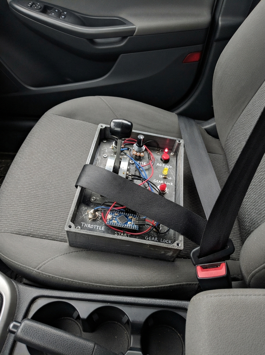
This guide builds a flight-simulator throttle quadrant controller using an Arduino Pro Mini. The project combines four potentiometer-based lever controls for engine throttles, spoilers, and flaps with three panel buttons for spoiler arm, autopilot disengage, and gear down functions. Status LEDs indicate gear position and gear lock state, providing visual feedback during flight simulation.
Builders will receive a complete wiring diagram showing potentiometer and button connections, a full parts list with resistor values, step-by-step assembly instructions for mounting the lever controls and wiring the panel, and Arduino firmware that handles debounced button input and analog axis calibration. The controller communicates via USB as a standard joystick device, compatible with popular flight simulators.
Wiring diagram

Gather all the parts
Assemble it in 5 steps
1. Place the four lever controls
Use four 10 kΩ potentiometers for the levers. On each potentiometer, connect one outside leg to the Arduino Micro 5V pin and the other outside leg to GND. Connect the middle leg of the Engine 1 lever to A0, Engine 2 to A1, spoiler lever to A2, and flaps lever to A3.
- If a lever works backwards, swap its two outside wires; leave the middle wire where it is.
- Do not connect an outside potentiometer leg directly to an Arduino input pin; the middle leg is the signal wire.
2. Wire the three panel buttons
Connect one leg of the spoiler-arm button to D6 and its other leg to GND. Connect one leg of the autopilot-disengage button to D4 and its other leg to GND. Connect one leg of the landing-gear button to D8 and its other leg to GND.
- The program uses the Arduino's built-in pull-up resistors, so no extra resistor is needed for these buttons.
- Use the two button legs that are not already permanently joined together; if a button always reads as pressed, rotate it 90 degrees on the breadboard.
3. Wire the three gear-down lights
For each of the three green gear-down LEDs, connect D9 to a 1 kΩ resistor, then connect the resistor's free end to the LED's long leg. Connect each LED's short leg to GND. Each LED needs its own resistor even though all three are controlled from D9.
- The long LED leg is the positive leg; the shorter leg and flat side of the LED body mark the ground side.
- Do not join three LEDs directly to D9 without separate resistors — too much current can damage the LEDs or the Arduino pin.
4. Add the gear-lock light
Connect D10 to one lead of the new 1 kΩ resistor. Connect the resistor's other lead to the long leg of the green gear-lock LED. Connect that LED's short leg to GND. This light turns on with the gear-down control.
- Label this LED “GEAR LOCK” on the panel so it is easy to distinguish from the three gear-down lights.
- Make sure the resistor is between D10 and the LED long leg — connecting the LED straight to D10 can damage the LED or the Arduino pin.
5. Connect and test the USB controller
Check that every ground wire goes to an Arduino GND pin, then connect the Arduino Micro to the computer with a data-capable USB cable. The board becomes a USB joystick after you deploy the project.
- Before mounting the panel, test each lever and button while the electronics are still easy to reach.
- Do not use a charge-only USB cable; it powers the board but cannot send the joystick controls to the computer.
Review all connections
1. Connections between "engine1_throttle" and "Arduino"
2. Connections between "engine2_throttle" and "Arduino"
3. Connections between "spoiler_axis" and "Arduino"
4. Connections between "flaps_axis" and "Arduino"
5. Connections between "spoiler_arm_button" and "Arduino"
6. Connections between "autopilot_disengage_button" and "Arduino"
7. Connections between "landing_gear_button" and "Arduino"
8. Connections between "gear_led_resistor_1" and "Arduino"
9. Connections between "gear_led_1" and "Arduino"
10. Connections between "gear_led_resistor_2" and "Arduino"
11. Connections between "gear_led_2" and "Arduino"
12. Connections between "gear_led_resistor_3" and "Arduino"
13. Connections between "gear_led_3" and "Arduino"
14. Connections between "gear_lock_led_resistor" and "Arduino"
15. Connections between "gear_lock_led" and "Arduino"
Deploy the firmware
#include <Arduino.h>
#include <Joystick.h>

// Arduino Pro Micro USB flight-simulator throttle quadrant.
// Axes: X=Engine 1, Y=Engine 2, Rx=Spoiler, Ry=Flaps.
// Buttons: 0=Spoiler arm, 1=Autopilot disengage, 2=Gear down.


struct ButtonState {
  uint8_t pin;
  uint8_t joystickButton;
  bool lastReading;
  bool stableReading;
  unsigned long changedAt;
};


// Forward declarations
int readAxis(uint8_t pin);
void updateButton(ButtonState &button, bool isGearButton);
void updateAxes();

const uint8_t ENGINE1_PIN = A0;
const uint8_t ENGINE2_PIN = A1;
const uint8_t SPOILER_PIN = A2;
const uint8_t FLAPS_PIN = A3;
const uint8_t AUTOPILOT_DISENGAGE_PIN = 4;
const uint8_t SPOILER_ARM_PIN = 6;
const uint8_t GEAR_DOWN_PIN = 8;
const uint8_t GEAR_LED_PIN = 9;
const uint8_t GEAR_LOCK_LED_PIN = 10;

const unsigned long DEBOUNCE_MS = 25;
const unsigned long ANALOG_CHECK_MS = 20;

// Library 2.1.1 constructor: report ID, type, button count, hat count,
// then exactly 11 axis-enable flags: X, Y, Z, Rx, Ry, Rz, rudder,
// throttle, accelerator, brake, steering.
Joystick_ Joystick(JOYSTICK_DEFAULT_REPORT_ID, JOYSTICK_TYPE_JOYSTICK,
                  3, 0, true, true, false, true, true, false,
                  false, false, false, false, false);


ButtonState spoilerArm = {SPOILER_ARM_PIN, 0, HIGH, HIGH, 0};
ButtonState autopilotDisengage = {AUTOPILOT_DISENGAGE_PIN, 1, HIGH, HIGH, 0};
ButtonState gearDown = {GEAR_DOWN_PIN, 2, HIGH, HIGH, 0};

int lastEngine1 = -1;
int lastEngine2 = -1;
int lastSpoiler = -1;
int lastFlaps = -1;
unsigned long lastAnalogCheckAt = 0;

int readAxis(uint8_t pin) {
  return map(analogRead(pin), 0, 1023, 0, 1023);
}

void updateButton(ButtonState &button, bool isGearButton) {
  bool reading = digitalRead(button.pin);
  unsigned long now = millis();

  if (reading != button.lastReading) {
    button.changedAt = now;
    button.lastReading = reading;
  }

  if ((now - button.changedAt) >= DEBOUNCE_MS && reading != button.stableReading) {
    button.stableReading = reading;
    bool pressed = (button.stableReading == LOW);
    Joystick.setButton(button.joystickButton, pressed);
    if (isGearButton) {
      // Pin 9 drives the three gear-down LEDs; pin 10 drives the gear-lock LED.
      digitalWrite(GEAR_LED_PIN, pressed ? HIGH : LOW);
      digitalWrite(GEAR_LOCK_LED_PIN, pressed ? HIGH : LOW);
    }
  }
}

void updateAxes() {
  int engine1 = readAxis(ENGINE1_PIN);
  int engine2 = readAxis(ENGINE2_PIN);
  int spoiler = readAxis(SPOILER_PIN);
  int flaps = readAxis(FLAPS_PIN);

  if (engine1 != lastEngine1) {
    lastEngine1 = engine1;
    Joystick.setXAxis(engine1);
  }
  if (engine2 != lastEngine2) {
    lastEngine2 = engine2;
    Joystick.setYAxis(engine2);
  }
  if (spoiler != lastSpoiler) {
    lastSpoiler = spoiler;
    Joystick.setRxAxis(spoiler);
  }
  if (flaps != lastFlaps) {
    lastFlaps = flaps;
    Joystick.setRyAxis(flaps);
  }
}

void setup() {
  pinMode(SPOILER_ARM_PIN, INPUT_PULLUP);
  pinMode(AUTOPILOT_DISENGAGE_PIN, INPUT_PULLUP);
  pinMode(GEAR_DOWN_PIN, INPUT_PULLUP);
  pinMode(GEAR_LED_PIN, OUTPUT);
  pinMode(GEAR_LOCK_LED_PIN, OUTPUT);
  digitalWrite(GEAR_LED_PIN, LOW);
  digitalWrite(GEAR_LOCK_LED_PIN, LOW);

  Joystick.setXAxisRange(0, 1023);
  Joystick.setYAxisRange(0, 1023);
  Joystick.setRxAxisRange(0, 1023);
  Joystick.setRyAxisRange(0, 1023);
  Joystick.begin(false);
  updateAxes();
  Joystick.sendState();
}

void loop() {
  updateButton(spoilerArm, false);
  updateButton(autopilotDisengage, false);
  updateButton(gearDown, true);

  unsigned long now = millis();
  if (now - lastAnalogCheckAt >= ANALOG_CHECK_MS) {
    lastAnalogCheckAt = now;
    updateAxes();
  }
}
Remix this project
Make it yours in one click
Open a full copy of this project in your own Schematik workspace — diagram, code, parts, and assembly steps included. Swap the sensor, add features, or redesign the whole thing with AI. The author's original stays untouched.