Community project
Autonomous 6x6 AI Rover
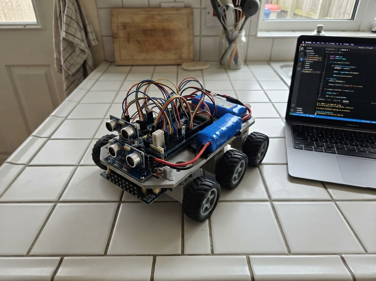
This autonomous 6x6 rover uses an ESP32-CAM controller to navigate and sense its environment with multiple sensor modes: line-following via a 4-channel IR array, obstacle avoidance with ultrasonic ranging, and environmental monitoring through temperature, humidity, and gas sensors. The rover is powered by a protected 3S Li-ion battery pack and dual motor drivers, enabling independent control of left and right track pairs for precise maneuverability.
This guide provides a complete parts list, wiring diagram, and step-by-step assembly instructions for building the rover's power distribution, motor control, sensor integration, and camera link. The included firmware implements mode switching between manual, line-following, and autonomous obstacle-avoidance behaviors, with telemetry streaming and command handling over serial. Safe staged power-up procedures ensure all subsystems are verified before autonomous operation.
Wiring diagram

Gather all the parts
Assemble it in 6 steps
1. Prepare the 3S protected power system
Use three matched 18650 cells in the holder and connect the holder only to the B+ and B- battery terminals of the 3S BMS. Route BMS protected output through an inline fuse and the main power switch, then into the dual buck regulator VIN terminals. Set the electronics buck to exactly 5.0 V and the motor buck to the verified N20 motor voltage (assumed 6.0 V here) before connecting electronics.
- Place the fuse as close as possible to battery positive.
- Measure both buck outputs with a multimeter before connecting the ESP32 or drivers.
- Use wire/connectors rated for the expected motor-stall current.
- Never charge 3S lithium cells with a single-cell charger.
- Do not mix cell brands, capacities, or states of charge.
- Do not proceed until the real motor voltage and aggregate stall current are verified.
2. Install motors and wire the two motor drivers
Mount the six N20 motors and wheels. Connect left front plus left middle motors in parallel to motor_driver_left channel A outputs; connect left rear motor to channel B outputs. Do the same on motor_driver_right for the right-side motors. Connect the 6 V motor rail to both VM pins, 3.3 V to both VCC pins, and all grounds to common ground.
- Temporarily label every motor lead before final harnessing.
- If a side runs backward during testing, swap that motor bank's two output wires rather than changing safety wiring.
- Add bulk capacitance close to each motor-driver VM/GND pair.
- TB6612FNG channels must not exceed their continuous or stall-current limit; parallel motors can overload a channel.
- Keep motor wiring physically separated from sensor and I2C wiring.
3. Wire the MCP23017 and motor-control signals
Connect MCP23017 VDD to 3.3 V, VSS to ground, SDA to ESP32 GPIO21, SCL to GPIO22, and RESET to 3.3 V. Connect GPA0–GPA3 to the left driver AIN1, AIN2, BIN1, BIN2; connect GPA4–GPA7 to the right driver AIN1, AIN2, BIN1, BIN2. Wire PWM and standby signals: left PWMA GPIO25, left PWMB GPIO26, left STBY GPIO27; right PWMA GPIO32, right PWMB GPIO33, right STBY GPIO5.
- Use short I2C wires and provide 3.3 V I2C pull-ups if your MCP23017 board lacks them.
- Keep all grounds joined at the regulated supply return.
- GPIO5 is a boot-strapping pin; ensure the right-driver STBY input does not force it low during reset. If boot becomes unreliable, explicitly change this frozen allocation before hardware revision.
4. Install and wire navigation and environmental sensors
Power the DHT22 and four-channel line sensor array from 3.3 V. Connect DHT22 DATA to GPIO4 with a 10 kΩ pull-up to 3.3 V if the module does not include one. Connect line D1/D2/D3/D4, left to right, to GPIO13/GPIO14/GPIO18/GPIO19. Power HC-SR04 and MQ-2 from 5 V. Connect ultrasonic TRIG to GPIO23 and ECHO through a 5 V-to-3.3 V resistor divider to GPIO15. Connect MQ-2 AO through another divider to GPIO35.
- Mount the line array low and parallel to the ground; adjust each comparator trimmer on the real line surface.
- Allow the MQ-2 heater to warm up before treating readings as relative trends.
- Keep the DHT22 away from warm regulators and the MQ-2 heater.
- Never connect HC-SR04 ECHO or MQ-2 AO directly to an ESP32 pin because these modules can output 5 V.
- MQ-2 readings are not calibrated gas concentration or a life-safety alarm.
5. Install the camera node and serial link
Power the ESP32-CAM AI Thinker from the regulated 5 V rail and common ground. Cross the UART: master GPIO17 TX goes to ESP32-CAM U0R, and master GPIO16 RX goes to ESP32-CAM U0T. Mount the camera where motor vibration is minimized and keep its antenna/camera area clear.
- Use a 5 V supply capable of ESP32-CAM current peaks.
- Flash and bench-test the camera node separately before connecting the UART.
- UART lines are 3.3 V logic only.
- Do not power the ESP32-CAM from the DevKit 3.3 V pin.
6. Perform safe staged power-up and functional tests
With wheels raised off the bench, power the rover and confirm 5 V and 3.3 V rails. Deploy the master firmware with Schematik, verify the MCP23017 startup check, then test STOP and MANUAL movement commands one motor bank at a time. Confirm sensor telemetry before enabling LINE or AVOID modes. Calibrate line sensor polarity and thresholds after confirming all drive directions.
- Start at reduced PWM speed and test with the chassis lifted.
- Verify emergency STOP repeatedly before floor testing.
- Use a clear test area for obstacle avoidance.
- Keep hands, wires, and clothing clear of wheels.
- Disconnect the battery before changing motor, power, or driver wiring.
Review all connections
1. Connections between "battery_pack" and "ESP32"
2. Connections between "bms" and "ESP32"
3. Connections between "power_regulator" and "ESP32"
4. Connections between "motor_driver_left" and "ESP32"
5. Connections between "motor_driver_right" and "ESP32"
6. Connections between "gpio_expander" and "ESP32"
7. Connections between "ultrasonic" and "ESP32"
8. Connections between "environment" and "ESP32"
9. Connections between "line_sensor" and "ESP32"
10. Connections between "gas_sensor" and "ESP32"
11. Connections between "camera_node" and "ESP32"
Deploy the firmware
#include <Arduino.h>
#include <Wire.h>
#include <Adafruit_MCP23X17.h>
#include <DHT.h>


// Hoisted type definitions
enum RoverMode { STOPPED, MANUAL, LINE_FOLLOW, AVOID };


// Forward declarations
void setDirections(bool leftForward, bool rightForward);
void setMotorPwm(uint8_t leftSpeed, uint8_t rightSpeed);
void drive(int leftSpeed, int rightSpeed);
void emergencyStop();
long readDistanceCm();
void lineFollowStep();
void obstacleAvoidStep();
void sendTelemetry();
void handleCommand(String command);
void pollCommands(Stream &port, String &buffer);

constexpr uint8_t LEFT_A_PWM = 25, LEFT_B_PWM = 26, LEFT_STBY = 27;
constexpr uint8_t RIGHT_A_PWM = 32, RIGHT_B_PWM = 33, RIGHT_STBY = 5;
constexpr uint8_t ULTRASONIC_TRIG = 23, ULTRASONIC_ECHO = 15;
constexpr uint8_t DHT_PIN = 4, GAS_ADC = 35;
constexpr uint8_t LINE_LEFT_OUTER = 13, LINE_LEFT_INNER = 14;
constexpr uint8_t LINE_RIGHT_INNER = 18, LINE_RIGHT_OUTER = 19;
constexpr uint8_t CAMERA_RX = 16, CAMERA_TX = 17;
constexpr uint8_t MOTOR_SPEED = 150;
constexpr int OBSTACLE_LIMIT_CM = 25;

Adafruit_MCP23X17 mcp;
DHT dht(DHT_PIN, DHT22);
HardwareSerial cameraSerial(2);

RoverMode mode = STOPPED;
unsigned long lastAutonomyMs = 0, lastTelemetryMs = 0;

void setDirections(bool leftForward, bool rightForward) {
  mcp.digitalWrite(0, leftForward);  mcp.digitalWrite(1, !leftForward);
  mcp.digitalWrite(2, leftForward);  mcp.digitalWrite(3, !leftForward);
  mcp.digitalWrite(4, rightForward); mcp.digitalWrite(5, !rightForward);
  mcp.digitalWrite(6, rightForward); mcp.digitalWrite(7, !rightForward);
}

void setMotorPwm(uint8_t leftSpeed, uint8_t rightSpeed) {
  ledcWrite(LEFT_A_PWM, leftSpeed);  ledcWrite(LEFT_B_PWM, leftSpeed);
  ledcWrite(RIGHT_A_PWM, rightSpeed); ledcWrite(RIGHT_B_PWM, rightSpeed);
}

void drive(int leftSpeed, int rightSpeed) {
  setDirections(leftSpeed >= 0, rightSpeed >= 0);
  setMotorPwm(abs(leftSpeed), abs(rightSpeed));
  digitalWrite(LEFT_STBY, HIGH);
  digitalWrite(RIGHT_STBY, HIGH);
}

void emergencyStop() {
  setMotorPwm(0, 0);
  digitalWrite(LEFT_STBY, LOW);
  digitalWrite(RIGHT_STBY, LOW);
  mode = STOPPED;
}

long readDistanceCm() {
  digitalWrite(ULTRASONIC_TRIG, LOW); delayMicroseconds(3);
  digitalWrite(ULTRASONIC_TRIG, HIGH); delayMicroseconds(10);
  digitalWrite(ULTRASONIC_TRIG, LOW);
  unsigned long duration = pulseIn(ULTRASONIC_ECHO, HIGH, 30000);
  return duration ? duration / 58 : -1;
}

void lineFollowStep() {
  bool lo = digitalRead(LINE_LEFT_OUTER) == LOW;
  bool li = digitalRead(LINE_LEFT_INNER) == LOW;
  bool ri = digitalRead(LINE_RIGHT_INNER) == LOW;
  bool ro = digitalRead(LINE_RIGHT_OUTER) == LOW;
  if (li && ri) drive(MOTOR_SPEED, MOTOR_SPEED);
  else if (lo || li) drive(80, MOTOR_SPEED);
  else if (ro || ri) drive(MOTOR_SPEED, 80);
  else emergencyStop();
}

void obstacleAvoidStep() {
  long distance = readDistanceCm();
  if (distance > 0 && distance < OBSTACLE_LIMIT_CM) {
    drive(-130, -130); delay(250);
    drive(150, -150); delay(380);
  } else drive(MOTOR_SPEED, MOTOR_SPEED);
}

void sendTelemetry() {
  float humidity = dht.readHumidity();
  float temperature = dht.readTemperature();
  long distance = readDistanceCm();
  int gasRaw = analogRead(GAS_ADC);
  Serial.printf("TELEMETRY mode=%d distance_cm=%ld temp_c=%.1f humidity_pct=%.1f gas_raw=%d\n", mode, distance, temperature, humidity, gasRaw);
  cameraSerial.printf("STATUS mode=%d distance=%ld\n", mode, distance);
}

void handleCommand(String command) {
  command.trim(); command.toUpperCase();
  if (command == "STOP") emergencyStop();
  else if (command == "MANUAL") { emergencyStop(); mode = MANUAL; }
  else if (command == "LINE") mode = LINE_FOLLOW;
  else if (command == "AVOID") mode = AVOID;
  else if (command == "FWD" && mode == MANUAL) drive(MOTOR_SPEED, MOTOR_SPEED);
  else if (command == "REV" && mode == MANUAL) drive(-MOTOR_SPEED, -MOTOR_SPEED);
  else if (command == "LEFT" && mode == MANUAL) drive(-MOTOR_SPEED, MOTOR_SPEED);
  else if (command == "RIGHT" && mode == MANUAL) drive(MOTOR_SPEED, -MOTOR_SPEED);
  else if (command == "CAM_ON") cameraSerial.println("STREAM_ON");
  else if (command == "CAM_OFF") cameraSerial.println("STREAM_OFF");
}

void pollCommands(Stream &port, String &buffer) {
  while (port.available()) {
    char c = static_cast<char>(port.read());
    if (c == '\n' || c == '\r') { if (buffer.length()) handleCommand(buffer); buffer = ""; }
    else if (buffer.length() < 48) buffer += c;
  }
}

void setup() {
  Serial.begin(115200);
  cameraSerial.begin(115200, SERIAL_8N1, CAMERA_RX, CAMERA_TX);
  Wire.begin(21, 22);
  if (!mcp.begin_I2C(0x20, &Wire)) {
    Serial.println("FATAL: MCP23017 not found; motors remain locked.");
    while (true) delay(1000);
  }
  for (uint8_t pin = 0; pin < 8; ++pin) { mcp.pinMode(pin, OUTPUT); mcp.digitalWrite(pin, LOW); }
  pinMode(LEFT_STBY, OUTPUT); pinMode(RIGHT_STBY, OUTPUT);
  pinMode(ULTRASONIC_TRIG, OUTPUT); pinMode(ULTRASONIC_ECHO, INPUT);
  pinMode(LINE_LEFT_OUTER, INPUT); pinMode(LINE_LEFT_INNER, INPUT);
  pinMode(LINE_RIGHT_INNER, INPUT); pinMode(LINE_RIGHT_OUTER, INPUT);
  ledcAttach(LEFT_A_PWM, 18000, 8); ledcAttach(LEFT_B_PWM, 18000, 8);
  ledcAttach(RIGHT_A_PWM, 18000, 8); ledcAttach(RIGHT_B_PWM, 18000, 8);
  dht.begin(); emergencyStop();
  Serial.println("Ready: STOP, MANUAL, FWD, REV, LEFT, RIGHT, LINE, AVOID, CAM_ON, CAM_OFF");
}

void loop() {
  static String usbBuffer, cameraBuffer;
  pollCommands(Serial, usbBuffer); pollCommands(cameraSerial, cameraBuffer);
  unsigned long now = millis();
  if (now - lastAutonomyMs >= 80) {
    lastAutonomyMs = now;
    if (mode == LINE_FOLLOW) lineFollowStep();
    if (mode == AVOID) obstacleAvoidStep();
  }
  if (now - lastTelemetryMs >= 3000) { lastTelemetryMs = now; sendTelemetry(); }
}
Remix this project
Make it yours in one click
Open a full copy of this project in your own Schematik workspace — diagram, code, parts, and assembly steps included. Swap the sensor, add features, or redesign the whole thing with AI. The author's original stays untouched.
Related projects

Create A Complete Electrical Schematic Esp32 Sma
ESP32 · September 17, 2026Ayansh Agrawal
ESP32 Kare Ekran Projeleri
ESP32 · September 16, 2026Seref Ai
Component Qty --------------------------- ------
ESP32 · September 16, 2026Yathartha Chakrawal