Community project
Bluetooth Media Remote
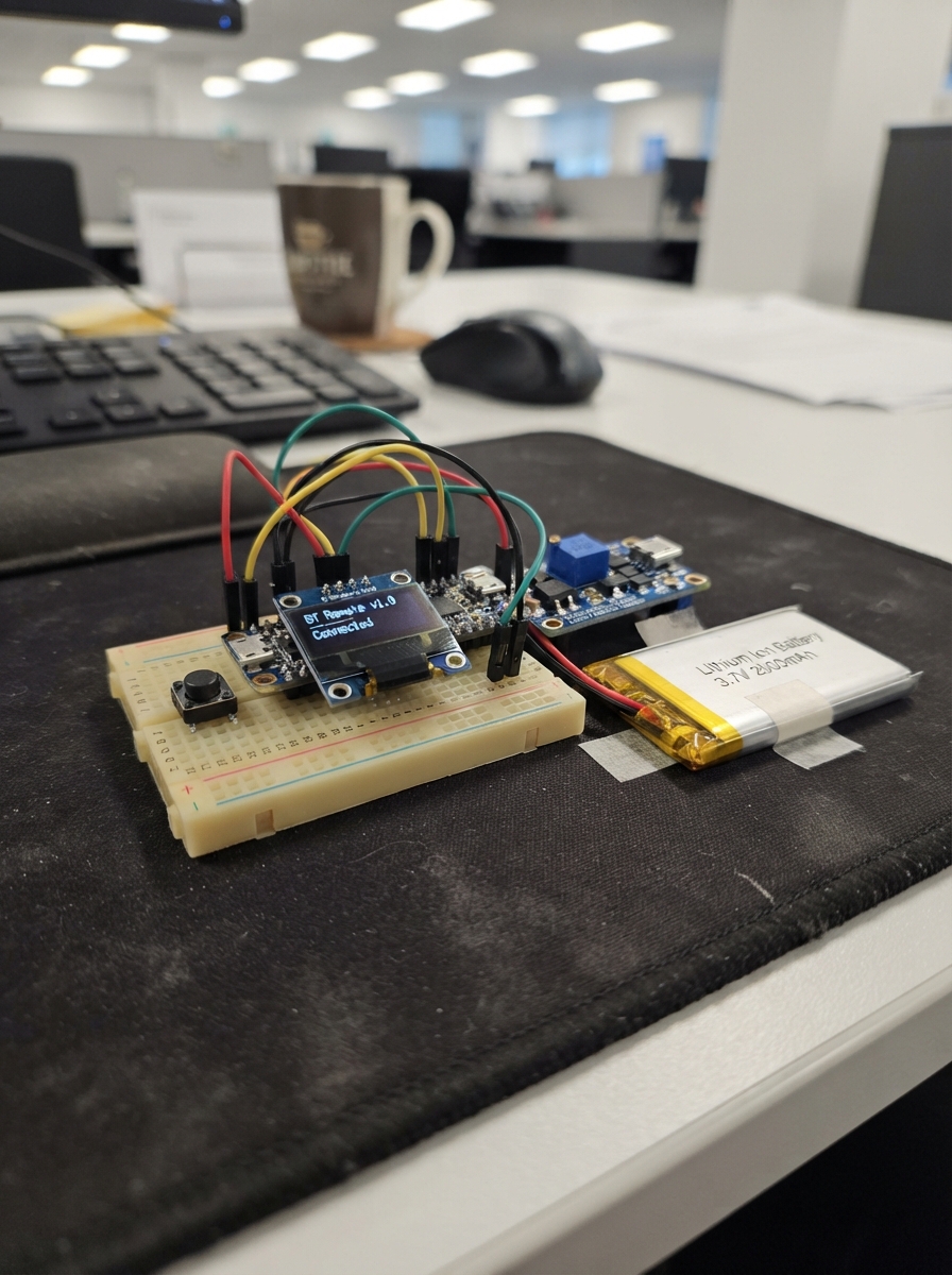
This Bluetooth media remote lets you control music playback and volume from across the room using an ESP32 microcontroller. The device pairs with phones, tablets, and computers via Bluetooth, sending standard media control commands for play/pause, track navigation, and volume adjustment through six tactile buttons.
The guide provides a complete wiring diagram, parts list, and step-by-step assembly instructions for building this battery-powered remote. A lithium-ion battery with integrated charging and fuel gauge monitoring ensures reliable operation, while an OLED display shows real-time battery status. The included firmware handles button debouncing and Bluetooth communication, ready to upload to the ESP32.
Wiring diagram

Gather all the parts
Assemble it in 5 steps
1. Order the carrier board
Order a two-layer carrier PCB with 1.6 mm thickness and standard 2.54 mm through-holes. It needs footprints for the ESP32 DevKit V1, the TP4056 protected charger module, the MT3608 boost module, the 0.96-inch OLED, the MAX17048 gauge board, and six 6 mm through-hole push buttons. Place the OLED at the top front edge, the six buttons below it in two rows of three, and keep the ESP32 antenna end at least 15 mm clear of copper, battery, charger, boost board, and metal mounting hardware so Bluetooth range stays strong.
- Use socket headers for the ESP32, OLED, and MAX17048 so a damaged module can be replaced without remaking the PCB.
- Put clear labels beside every connector and button: 3V3, GND, SDA, SCL, B+, B-, OUT+, OUT-, IN+, IN-, and the six button names.
- Do not route copper or place the battery underneath the ESP32 antenna end — this can greatly reduce Bluetooth range.
- This is a carrier board: do not put 5 V on any OLED or MAX17048 signal pin.
2. Route the power section
Put the TP4056 and MT3608 at one side of the PCB, away from the OLED and ESP32 antenna. Route battery positive from the battery connector to TP4056 B+ (battery positive) and battery negative to TP4056 B- (battery negative). Route TP4056 OUT+ to MT3608 IN+ (protected battery power) and TP4056 OUT- to MT3608 IN- (ground). Route MT3608 OUT+ to the ESP32 VIN/5V header pin (power) and MT3608 OUT- to the shared GND net (ground). Use wide traces, at least 1 mm, for every battery, charger-output, and 5 V boost path.
- Add a keyed two-pin JST-PH battery connector labelled BATTERY; it helps prevent connecting the cell backwards.
- Add two labelled test pads, 5V and GND, beside the boost output so you can measure it before fitting the ESP32.
- Set the MT3608 to exactly 5.0 V using the 5V and GND test pads before inserting the ESP32 — a higher voltage can damage the board.
- Use a protected TP4056 module with separate B+, B-, OUT+, and OUT- pads; do not substitute a four-pad charger module on this carrier board.
3. Route the screen and battery meter
Make a 3.3 V and GND area beside the OLED and MAX17048. Connect OLED VCC to ESP32 3V3 (power), OLED GND to GND (ground), OLED SDA to GPIO21 (data), and OLED SCL to GPIO22 (clock). Connect MAX17048 VIN to ESP32 3V3 (power), MAX17048 GND to GND (ground), MAX17048 SDA to GPIO21 (data), MAX17048 SCL to GPIO22 (clock), and MAX17048 BAT to TP4056 B+ (battery positive). Keep the BAT trace away from the MT3608 switching area.
- The OLED and battery gauge deliberately share the SDA and SCL traces; run one pair of traces and branch them to both headers.
- Use four-pin headers with the printed label order matching the actual module labels before soldering.
- Do not connect the MAX17048 BAT pin to the 5 V boost output — it measures the single battery cell directly and 5 V can damage it.
- Make sure VCC and GND are not swapped on the OLED or battery gauge headers — swapped power can damage either module.
4. Fit and route the six buttons
Give each button one pad on the shared GND copper area (ground). Route the other pad of each button to its ESP32 header pin: Play/Pause to GPIO4 (signal), Next to GPIO13 (signal), Previous to GPIO14 (signal), Volume Up to GPIO16 (signal), Volume Down to GPIO17 (signal), and Mute to GPIO18 (signal). Place the button labels on the front silkscreen so the remote is readable when held upright.
- Use the two button pins that are not already joined internally; with a common 6 mm push button these are opposite sides of the switch.
- A large ground copper fill on both PCB layers makes these button connections easy and reliable.
- Do not connect a button signal pad to 3.3 V or 5 V — each press must connect its ESP32 pin to ground.
- Check the footprint against one real button before ordering; different push-button bodies can have different pin spacing.
5. Assemble and check the carrier
Solder the low-profile parts first: button switches, battery connector, and test pads. Then fit the socket headers for the ESP32, OLED, MAX17048, TP4056, and MT3608. Insert the modules only after inspecting for solder bridges. Connect the battery, set the boost output to exactly 5.0 V, then insert the ESP32, OLED, and gauge. The TP4056 USB connector must remain reachable from the case opening so the remote can be recharged.
- Before installing the ESP32, use a multimeter between the PCB 5V and GND test pads; it should read 5.0 V.
- A simple plastic enclosure with a front OLED window and six button holes protects the PCB and battery.
- Never charge a damaged, swollen, or unusually hot lithium battery.
- Do not connect a USB cable to the ESP32 and the TP4056 charging input at the same time unless you have confirmed both supplies share a safe common ground and you understand the power path.
Review all connections
1. Connections between "play_pause_button" and "ESP32"
2. Connections between "next_button" and "ESP32"
3. Connections between "previous_button" and "ESP32"
4. Connections between "volume_up_button" and "ESP32"
5. Connections between "volume_down_button" and "ESP32"
6. Connections between "mute_button" and "ESP32"
7. Connections between "battery_3v7_2000mah" and "ESP32"
8. Connections between "tp4056_charger" and "ESP32"
9. Connections between "boost_5v" and "ESP32"
10. Connections between "oled_096" and "ESP32"
11. Connections between "battery_gauge" and "ESP32"
Deploy the firmware
#include <Arduino.h>
#include <Wire.h>
#include <BleKeyboard.h>
#include <Adafruit_GFX.h>
#include <Adafruit_SSD1306.h>
#include <Adafruit_MAX1704X.h>

struct MediaButton {
  int pin;
  uint8_t key;
  bool previousReading;
  bool stableState;
  unsigned long changedAt;
};


// Forward declarations
void showBatteryStatus();
void updateBatteryDisplay(unsigned long now);

const int PLAY_PAUSE_PIN = 4;
const int NEXT_PIN = 13;
const int PREVIOUS_PIN = 14;
const int VOLUME_UP_PIN = 16;
const int VOLUME_DOWN_PIN = 17;
const int MUTE_PIN = 18;
const int I2C_SDA_PIN = 21;
const int I2C_SCL_PIN = 22;
const unsigned long DEBOUNCE_MS = 30;
const unsigned long BATTERY_CHECK_MS = 5000;

BleKeyboard bleKeyboard("Schematik Media Remote", "Schematik", 100);
Adafruit_SSD1306 display(128, 64, &Wire, -1);
Adafruit_MAX17048 batteryGauge;
bool displayReady = false;
bool gaugeReady = false;
int lastShownPercent = -1;
int lastShownTenths = -1;
unsigned long lastBatteryCheck = 0;

MediaButton buttons[] = {
  {PLAY_PAUSE_PIN, KEY_MEDIA_PLAY_PAUSE, HIGH, HIGH, 0},
  {NEXT_PIN, KEY_MEDIA_NEXT_TRACK, HIGH, HIGH, 0},
  {PREVIOUS_PIN, KEY_MEDIA_PREVIOUS_TRACK, HIGH, HIGH, 0},
  {VOLUME_UP_PIN, KEY_MEDIA_VOLUME_UP, HIGH, HIGH, 0},
  {VOLUME_DOWN_PIN, KEY_MEDIA_VOLUME_DOWN, HIGH, HIGH, 0},
  {MUTE_PIN, KEY_MEDIA_MUTE, HIGH, HIGH, 0}
};

void showBatteryStatus() {
  if (!displayReady) return;

  display.clearDisplay();
  display.setTextColor(SSD1306_WHITE);
  display.setTextSize(1);
  display.setCursor(0, 0);
  display.println("Media Remote");
  display.drawLine(0, 12, 127, 12, SSD1306_WHITE);

  if (!gaugeReady) {
    display.setCursor(0, 25);
    display.println("Battery gauge");
    display.println("not found");
  } else {
    float voltage = batteryGauge.cellVoltage();
    float percent = batteryGauge.cellPercent();
    if (percent < 0) percent = 0;
    if (percent > 100) percent = 100;

    display.setTextSize(2);
    display.setCursor(0, 22);
    display.print((int)(percent + 0.5f));
    display.print("%");
    display.setTextSize(1);
    display.setCursor(0, 49);
    display.print(voltage, 2);
    display.print(" V battery");
  }
  display.display();
}

void updateBatteryDisplay(unsigned long now) {
  if (!displayReady || now - lastBatteryCheck < BATTERY_CHECK_MS) return;
  lastBatteryCheck = now;

  if (!gaugeReady) {
    if (lastShownPercent != -2) {
      lastShownPercent = -2;
      showBatteryStatus();
    }
    return;
  }

  float percent = batteryGauge.cellPercent();
  float voltage = batteryGauge.cellVoltage();
  int roundedPercent = constrain((int)(percent + 0.5f), 0, 100);
  int tenthsVolt = (int)(voltage * 10.0f + 0.5f);
  if (roundedPercent != lastShownPercent || tenthsVolt != lastShownTenths) {
    lastShownPercent = roundedPercent;
    lastShownTenths = tenthsVolt;
    showBatteryStatus();
  }
}

void setup() {
  for (MediaButton &button : buttons) {
    pinMode(button.pin, INPUT_PULLUP);
  }

  Wire.begin(I2C_SDA_PIN, I2C_SCL_PIN);
  displayReady = display.begin(SSD1306_SWITCHCAPVCC, 0x3C);
  gaugeReady = batteryGauge.begin();
  showBatteryStatus();
  bleKeyboard.begin();
}

void loop() {
  unsigned long now = millis();
  updateBatteryDisplay(now);

  for (MediaButton &button : buttons) {
    bool reading = digitalRead(button.pin);
    if (reading != button.previousReading) {
      button.changedAt = now;
      button.previousReading = reading;
    }

    if (now - button.changedAt >= DEBOUNCE_MS && reading != button.stableState) {
      button.stableState = reading;
      if (button.stableState == LOW && bleKeyboard.isConnected()) {
        bleKeyboard.write(button.key);
      }
    }
  }
}
Remix this project
Make it yours in one click
Open a full copy of this project in your own Schematik workspace — diagram, code, parts, and assembly steps included. Swap the sensor, add features, or redesign the whole thing with AI. The author's original stays untouched.
Related projects

Create A Complete Electrical Schematic Esp32 Sma
ESP32 · September 17, 2026Ayansh Agrawal
ESP32 Kare Ekran Projeleri
ESP32 · September 16, 2026Seref Ai
Component Qty --------------------------- ------
ESP32 · September 16, 2026Yathartha Chakrawal