Community project
Bueno Entonces Creamos El Control Tmb O Lo
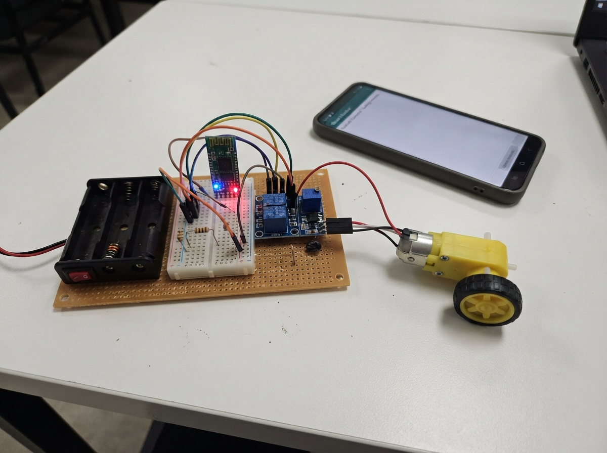
This guide builds a Bluetooth-controlled robot truck powered by an Arduino Uno and HC-05 wireless module. Two TT motors with 1:90 gearboxes drive the wheels, controlled through a TB6612FNG dual motor driver that handles direction and speed. The truck receives commands from a phone or tablet over Bluetooth, making it a fun introduction to wireless robotics and motor control.
The guide provides a complete wiring diagram, parts list, and Arduino firmware with command handling logic. Assembly covers motor mounting, safe power sequencing with the buck converter, proper motor driver connections, and Bluetooth module integration with level-shifting resistors. Testing steps ensure the truck responds correctly to phone controls before deployment.
Wiring diagram

Gather all the parts
Assemble it in 7 steps
1. Mount the moving parts
Fix left_motor on the left side of the truck chassis and right_motor on the right side, with their shafts facing the wheels. Attach the wheels so both motors push the truck forward when they turn the same way.
- Do not glue the motors until you have tested which direction each wheel turns.
- Keep fingers, loose wires, and hair away from the wheels when battery power is connected.
2. Set the power voltage before connecting electronics
With the battery holder switched off, connect its red VOUT wire to motor_regulator VIN+ and its black GND wire to motor_regulator VIN-. Turn the regulator's small adjustment screw while measuring VOUT+ and VOUT- with a multimeter, and stop at exactly 5.0 V. Switch the battery holder off again.
- The regulator's input side is marked VIN and its output side is marked VOUT.
- Do not connect the regulator output to the Arduino or motors until it reads 5.0 V; a higher setting can damage them.
3. Connect the shared power wires
Run motor_regulator VOUT+ to the Arduino 5V pin, TB6612FNG VM, TB6612FNG VCC, and bluetooth_hc05 Vcc (power). Run motor_regulator VOUT- to Arduino GND, TB6612FNG GND, and bluetooth_hc05 GND (ground). All of these ground wires must meet; without the shared ground, the commands cannot be understood.
- Connect the regulated 5 V output to the Arduino 5V pin, not VIN; VIN expects a higher unregulated voltage. Make sure 5V and GND are not swapped — swapped power can damage the modules.
4. Wire the two motors to the driver
Connect left_motor M1 to motor_driver A01 and left_motor M2 to motor_driver A02 (left-wheel power). Connect right_motor M1 to motor_driver B01 and right_motor M2 to motor_driver B02 (right-wheel power).
- If forward makes one wheel turn backward, switch that motor's two wires after switching the battery holder off.
5. Wire the driver control pins
Connect motor_driver AIN1 to Arduino D2 (left direction), PWMA to D3 (left speed), AIN2 to D4 (left direction), PWMB to D5 (right speed), STBY to D6 (driver enable), BIN1 to D7 (right direction), and BIN2 to D8 (right direction).
- Follow the pin labels printed on your TB6612FNG board; D3 and D5 are the two speed-control wires.
6. Wire the Bluetooth module safely
Connect bluetooth_hc05 TX to Arduino D10 (data). Connect Arduino D11 to one lead of rx_resistor_top; connect its other lead to bluetooth_hc05 RX. From that same bluetooth_hc05 RX point, connect one lead of rx_resistor_bottom, then connect its other lead to GND. This pair of resistors lowers the Arduino's 5 V signal to a safer level for the Bluetooth receive pin.
- The 1 kΩ resistor goes from D11 to RX; the 2 kΩ resistor goes from RX to GND.
- Do not connect Arduino D11 straight to the HC-05 RX pin; that direct 5 V signal can damage the Bluetooth module.
7. Test the phone controls
Switch on the battery holder, pair your phone with the HC-05 (many modules use PIN 1234 or 0000), then use a Bluetooth serial-controller app that sends single characters. Make buttons that send F for forward, B for backward, L for left, R for right, and S for stop.
- The truck stops automatically about half a second after commands stop arriving, which helps if Bluetooth disconnects.
- Lift the wheels off the table for the first test so the truck cannot drive away unexpectedly.
Review all connections
1. Connections between "main_battery" and "Arduino"
2. Connections between "motor_regulator" and "Arduino"
3. Connections between "bluetooth_hc05" and "Arduino"
4. Connections between "rx_resistor_top" and "Arduino"
5. Connections between "rx_resistor_bottom" and "Arduino"
6. Connections between "motor_driver" and "Arduino"
7. Connections between "left_motor" and "Arduino"
8. Connections between "right_motor" and "Arduino"
Deploy the firmware
#include <Arduino.h>

// Forward declarations
void setMotor(uint8_t in1, uint8_t in2, uint8_t pwm, int speedValue);
int readBluetoothByte();
void stopTruck();
void drive(int leftSpeed, int rightSpeed);
void handleCommand(char command);

const uint8_t LEFT_IN1 = 2;
const uint8_t LEFT_PWM = 3;
const uint8_t LEFT_IN2 = 4;
const uint8_t RIGHT_PWM = 5;
const uint8_t DRIVER_STBY = 6;
const uint8_t RIGHT_IN1 = 7;
const uint8_t RIGHT_IN2 = 8;
const uint8_t BT_TX_TO_ARDUINO = 10;
const uint8_t ARDUINO_TX_TO_BT = 11;

const uint8_t DRIVE_SPEED = 210;
const unsigned long COMMAND_TIMEOUT_MS = 600;

unsigned long lastCommandAt = 0;

void setMotor(uint8_t in1, uint8_t in2, uint8_t pwm, int speedValue) {
  if (speedValue > 0) {
    digitalWrite(in1, HIGH);
    digitalWrite(in2, LOW);
  } else if (speedValue < 0) {
    digitalWrite(in1, LOW);
    digitalWrite(in2, HIGH);
  } else {
    digitalWrite(in1, LOW);
    digitalWrite(in2, LOW);
  }
  analogWrite(pwm, abs(speedValue));
}

void stopTruck() {
  setMotor(LEFT_IN1, LEFT_IN2, LEFT_PWM, 0);
  setMotor(RIGHT_IN1, RIGHT_IN2, RIGHT_PWM, 0);
}

void drive(int leftSpeed, int rightSpeed) {
  digitalWrite(DRIVER_STBY, HIGH);
  setMotor(LEFT_IN1, LEFT_IN2, LEFT_PWM, leftSpeed);
  setMotor(RIGHT_IN1, RIGHT_IN2, RIGHT_PWM, rightSpeed);
}

// Receives the HC-05's 9600-baud, 8N1 command stream on GPIO10.
// Transmission to the module is not needed for the truck controls.
int readBluetoothByte() {
  if (digitalRead(BT_TX_TO_ARDUINO) != LOW) return -1;

  const unsigned int bitTimeUs = 104;
  delayMicroseconds(bitTimeUs + bitTimeUs / 2);
  uint8_t value = 0;
  for (uint8_t bit = 0; bit < 8; ++bit) {
    if (digitalRead(BT_TX_TO_ARDUINO) == HIGH) value |= (1 << bit);
    delayMicroseconds(bitTimeUs);
  }
  delayMicroseconds(bitTimeUs);  // stop bit
  return value;
}

void handleCommand(char command) {
  switch (command) {
    case 'F': case 'f': drive(DRIVE_SPEED, DRIVE_SPEED); break;
    case 'B': case 'b': drive(-DRIVE_SPEED, -DRIVE_SPEED); break;
    case 'L': case 'l': drive(-DRIVE_SPEED, DRIVE_SPEED); break;
    case 'R': case 'r': drive(DRIVE_SPEED, -DRIVE_SPEED); break;
    case 'S': case 's': stopTruck(); break;
    default: return;
  }
  lastCommandAt = millis();
}

void setup() {
  pinMode(LEFT_IN1, OUTPUT);
  pinMode(LEFT_IN2, OUTPUT);
  pinMode(LEFT_PWM, OUTPUT);
  pinMode(RIGHT_IN1, OUTPUT);
  pinMode(RIGHT_IN2, OUTPUT);
  pinMode(RIGHT_PWM, OUTPUT);
  pinMode(DRIVER_STBY, OUTPUT);
  digitalWrite(DRIVER_STBY, HIGH);
  stopTruck();

  pinMode(BT_TX_TO_ARDUINO, INPUT);
  pinMode(ARDUINO_TX_TO_BT, OUTPUT);
  digitalWrite(ARDUINO_TX_TO_BT, HIGH);
  lastCommandAt = millis();
}

void loop() {
  int received = readBluetoothByte();
  if (received >= 0) {
    handleCommand((char)received);
  }

  if (millis() - lastCommandAt > COMMAND_TIMEOUT_MS) {
    stopTruck();
  }
}
Remix this project
Make it yours in one click
Open a full copy of this project in your own Schematik workspace — diagram, code, parts, and assembly steps included. Swap the sensor, add features, or redesign the whole thing with AI. The author's original stays untouched.