Community project
Build Me Complete Schematic Esp-idf Firmware Ske
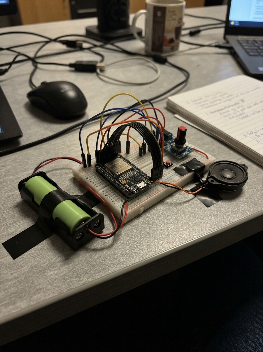
This guide walks through building a complete ESP32-based audio device with rotary encoder volume control and push-button inputs. The project combines an 18650 Li-ion battery, 8Ω speaker, KY-040 rotary encoder module, and push buttons into a functional unit powered by ESP-IDF firmware.
The guide provides a complete wiring diagram, detailed assembly steps, parts list, and ready-to-use ESP-IDF firmware. Follow the step-by-step instructions to connect the battery and speaker, adapt the GPIO headers, wire the volume knob and buttons, then power up and test the assembled device.
Wiring diagram

Gather all the parts
Assemble it in 6 steps
1. Check the board version and sockets
Use only a board whose back silkscreen says Rev2.0. Find the narrow 28-pin 1.27 mm GPIO header, the white SH1.0 speaker socket, and the two-pin MX1.25 battery socket. Do not connect ordinary 2.54 mm jumper plugs directly to the narrow GPIO header.
- The V2 has no black rotary knob; the separate EC11 part is required.
- Set the board Battery Switch off before connecting the battery.
- Using a 2.54 mm jumper directly on the 1.27 mm header can bend or short the tiny pins.
2. Connect battery and speaker
Plug the Molicel lead into the board’s MX1.25 battery socket with red on BAT+ and black on BAT−. Plug the speaker cable into the SH1.0 socket; the board socket uses pins 1 SPK+ and 2 SPK−, while pins 3 and 4 are unused.
- The keyed plugs should slide in without force.
- The included 8 Ω speaker is the safer backup choice for this first build.
- Do not reverse the battery lead — reversed battery power can damage the board.
- Do not connect either speaker wire to GND; both wires go only to the SH1.0 speaker socket.
3. Fit the GPIO adapter
Plug the 1.27 mm side of the adapter into the board’s 28-pin GPIO header, then use the 2.54 mm side as the landing point for the M-F jumper leads. This adapter is in-line between the board header and every external control wire.
- If a small adapter came in the Waveshare box, compare its pitch before using it.
- Keep the adapter strain-relieved so it cannot pull sideways on the fine-pitch header.
- A shifted adapter position can put a signal onto the wrong board pin and can damage the board.
4. Wire the volume knob
Wire the EC11 from the adapter: VCC → 3V3 (power), GND → GND (ground), A/CLK → GPIO6 (turn signal), B/DT → GPIO7 (turn direction signal), and SW → GPIO8 (push signal).
- The firmware turns on pull-ups, so no separate resistors are needed for the knob.
- Use five separate jumper leads and keep A and B beside each other to make tracing easier.
- Do not use GPIO2 or GPIO15 for the knob — those are already needed by the onboard audio hardware.
5. Wire the three buttons
Put each 6×6 mm button across the breadboard’s center gap. Join one leg of each button to one shared GND wire (ground). Connect the other legs: Cancel → GPIO9 (cancel signal), Action → GPIO12 (talk/action signal), Back → GPIO13 (back signal).
- On a tactile switch, the two legs on the same side are already joined; use legs from opposite sides.
- A press is read when the GPIO is connected to the shared GND wire.
- If a button is rotated 90 degrees incorrectly, both wires may land on already-connected legs and the button will never change state.
6. Power and test the assembled unit
Place the board, speaker, knob, and buttons where they cannot short against metal. Turn on the Battery Switch, plug USB-C into a 5 V 1 A wall adapter, and then use the board’s USB connection for deployment.
- USB-C is the normal power source; the battery is the deep-sleep backup and charges through the board.
- Build one unit fully first, then repeat the same wire colors and layout for the other two.
- Make sure VCC and GND are not swapped — swapped power can damage the board or external controls.
Review all connections
1. Connections between "gpio_adapter" and "ESP32"
2. Connections between "encoder" and "ESP32"
3. Connections between "button_cancel" and "ESP32"
4. Connections between "button_action" and "ESP32"
5. Connections between "button_back" and "ESP32"
6. Connections between "speaker" and "ESP32"
7. Connections between "battery_18650" and "ESP32"
Deploy the firmware
#include "freertos/FreeRTOS.h"
#include "freertos/task.h"
#include "driver/i2c_master.h"
#include "esp_event.h"
#include "esp_log.h"
#include "esp_netif.h"
#include "nvs_flash.h"
#include "board_pins.h"

void input_handler_init(void);
void audio_capture_init(void);
void audio_playback_init(void);
void display_renderer_init(void);
void display_renderer_set_mood(unsigned mood);
void ws_client_start(void);
void power_mgr_init(void);

static const char *TAG = "home_companion";

static void i2c0_init(void)
{
    i2c_master_bus_config_t cfg = {
        .i2c_port = I2C_NUM_0, .sda_io_num = PIN_I2C0_SDA,
        .scl_io_num = PIN_I2C0_SCL, .clk_source = I2C_CLK_SRC_DEFAULT,
        .glitch_ignore_cnt = 7, .flags.enable_internal_pullup = true,
    };
    i2c_master_bus_handle_t bus = NULL;
    ESP_ERROR_CHECK(i2c_new_master_bus(&cfg, &bus));
    ESP_LOGI(TAG, "I2C0 ready: CST816=0x%02X TCA9554=0x%02X RTC=0x%02X IMU=0x%02X ES8311=0x%02X ES7210=0x%02X", I2C_ADDR_CST816, I2C_ADDR_TCA9554, I2C_ADDR_PCF85063, I2C_ADDR_QMI8658, I2C_ADDR_ES8311, I2C_ADDR_ES7210);
}

static void network_init(void)
{
    ESP_ERROR_CHECK(esp_netif_init());
    ESP_ERROR_CHECK(esp_event_loop_create_default());
    /* Provision Wi-Fi credentials into encrypted NVS before field deployment. */
}

void app_main(void)
{
    ESP_ERROR_CHECK(nvs_flash_init());
    i2c0_init();
    power_mgr_init();
    input_handler_init();
    audio_capture_init();
    audio_playback_init();
    display_renderer_init();
    display_renderer_set_mood(0);
    network_init();
    ws_client_start();
    ESP_LOGI(TAG, "Home Companion v0.3 POC initialized");
    for (;;) vTaskDelay(pdMS_TO_TICKS(1000));
}
Remix this project
Make it yours in one click
Open a full copy of this project in your own Schematik workspace — diagram, code, parts, and assembly steps included. Swap the sensor, add features, or redesign the whole thing with AI. The author's original stays untouched.