Community project
Build Me Raspberry Pi Dual Screen Cyberdeck Like
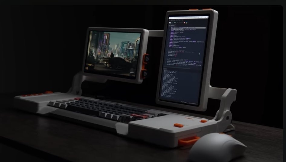
This guide builds a Raspberry Pi Pico-based control panel for a dual-screen cyberdeck, featuring dual rotary encoders for volume and scroll control, four programmable macro keys, and a capacitive trackpad interface. The project combines custom PCBs, 3D-printed mechanical components, and analog input electronics into a compact, professional-grade input device that communicates with a Raspberry Pi 5 host system via USB.
Builders will receive a complete wiring diagram, detailed parts list, CircuitPython firmware with HID keyboard and mouse support, and step-by-step assembly instructions covering PCB population, mechanical assembly, enclosure construction, and functional verification. The modular design allows customization of macro key bindings and encoder behavior through straightforward firmware edits.
Wiring diagram

Gather all the parts
Assemble it in 11 steps
1. Observe the Sector 07 license and collect the released packages
Build this as a personal, non-commercial project under the CC BY-NC 4.0 license: credit Sector 07 and do not sell the design or derivative files. Download the Sector 07 RPI_DEV 3D-print archive, editable base STEP archive, Gerber/order archives for PCB1–PCB4, matching PCB order-parameter PDFs, and the original BOM. Use the original BOM as the authority for exact monitor, keyboard, cable, connector, and Raspberry Pi 5 variants.
- The required-only budget supplied is about $728.14 before shipping, tax, and unlisted filament.
- PCB4 is an optional USB passthrough board; PCB1, PCB2, and PCB3 are required.
- This project is an integration record for the Pi 5 cyberdeck. Schematik deploys only the optional Raspberry Pi Pico controller, not the Raspberry Pi 5 Linux operating system.
- Do not substitute a monitor or PCB revision without checking it against Sector 07's original BOM and CAD.
2. Print the complete Sector 07 enclosure set
Print the 42 released STL pieces at 0.2 mm layer height with 20% infill, supports where the model requires them, and ironing on flat visible surfaces. Use grey/white matte PLA for normal body pieces and orange PLA for accents where intended. Print the left, center, and right base; six base I/O parts; eight housing/panel parts; nine button/control parts; four cable/port parts; two front and two back monitor cases; the five rotary/arm parts; and the three monitor-support parts.
- Use 80% infill for the printed monitor arms; the remaining regular parts use 20%.
- Start printing before electronics work because the enclosure is the longest lead-time portion.
- Use the eight released base/housing STEP files only if a physical part must be modified before printing.
- Clean all support-contact surfaces before attempting the base snap-tabs. The pieces should be snug, never forced.
- Do not use the Pi 4 version of Eject Two; print/use the Pi 5 Eject Two.
3. Install inserts and prepare mechanical hardware
Install the specified M3 heat-set inserts in the printed parts with a temperature-controlled soldering iron. Collect the exact M3/M5 fasteners, M5 locknuts, 12 mm dowel pins, ball bearings, and threadlocker listed by Sector 07. Tap only the locations the designer specifies, including the center-brace M5 holes and the monitor-arm M3 holes.
- Drive each insert straight and flush; let the plastic cool fully before installing screws.
- A very small amount of bearing grease in the roller channels is optional and may reduce noise.
- Do not tap beyond the specified thread depth; overshooting can split or strip the printed part.
- Keep grease away from monitor panels, cable contacts, and plastic snap joints.
4. Order and populate the custom PCB set
Order PCB1, PCB2, and PCB3 from their released Gerber archives using the corresponding Sector 07 order-parameter PDFs; order PCB4 only if you want the external USB passthrough. Populate PCB1 with the MOSFET, DIP switch, pushbuttons, FPC connector, Qwiic connector, and 18 AWG power leads. Populate PCB2 with its extended header, Qwiic connector, and FPC connector. Populate PCB3 with the 5 V barrel jack, Qwiic connector, FPC connector, and right-angle header. PCB4 needs its specified male USB connector.
- Use flux, magnification, a fine tip, and continuity testing for every FPC connector.
- Use an FPC breakout/test fixture to check for adjacent-pin shorts and opens before installation.
- FPC connectors are fine-pitch and hand-solder-hostile; do not power a board until it has passed a visual inspection and continuity test.
- PCB3 is for regulated 5 V only; never inject an unregulated battery or 9–12 V source.
5. Prepare the hub and analog-control electronics
Following the released Sector 07 diagram, prepare the specified internal USB hub: remove its stock 5 V barrel jack and USB 3.0 jack only if your exact BOM-specified hub and the released instructions require this modification. Leave enough of the factory USB cable to reach the Pi, solder its specified 18 AWG power leads, and build the female-to-male USB breakout cable as documented. Desolder the rotary-encoder header and solder its ribbon directly. Solder three leads to the linear potentiometer, then connect it to the PCF8591 analog-to-I2C module.
- Use short factory-made HDMI/USB assemblies for high-speed links; do not hand-wire USB or HDMI signal pairs.
- Label each power, USB, FPC, and Qwiic cable before routing it into the base.
- Hub modifications void its warranty and can destroy the hub if pad polarity or cable shielding is wrong.
- Keep the 5 V power wiring physically separate from fine FPC and Qwiic wiring where possible.
6. Assemble both monitor modules and rotating arms
Install inserts in the rotary mounts; attach the support arm to the left and right rotary mounts with M5 × 10 mm flat-head screws. Insert ball bearings into the channels, attach each back case to its rotary mount at the center holes, and temporarily retain printed buttons with painter's tape. Angle each exact BOM-specified monitor into its front case, respecting the half-circle PCB clearances, then snap the back-case/rotary assembly evenly onto it. Fit the HDMI and USB 90-degree adapters, route the cables through the arms and cable support with rotation slack, add arm covers, and install 12 mm dowel pins.
- Test monitor-arm movement through its full intended range before closing the arm covers.
- Leave a gentle cable loop at every moving joint to prevent fatigue.
- Monitor arm covers are fragile; begin installation at the 90-degree bend and avoid prying.
- Do not pinch HDMI or USB cables in the rotary channels.
7. Build the base and install internal boards
Snap the three base shells together through their 90-degree tabs after removing all support remnants. Route monitor USB/HDMI leads through the arm channels. Insert the locking tab, install PCB2 at the required steep angle and rotate it down, then install the rotary encoder and its knob. Mount the USB breakout, PCB1/spacer assembly, and USB hub. Feed the labeled FPC, Qwiic, rotary, and power harnesses through the designated access slot and wireway, following the released electrical diagram exactly.
- The 500 mm FPC from PCB1 is tight by design; fold it lengthwise only as Sector 07 specifies and never crease its conductive traces.
- Measure monitor USB leads in place before cutting/soldering any intended power-injector assemblies.
- If a tab does not seat with modest pressure, stop and remove remaining support material or lightly sand the contact face.
- Never pull on an FPC by its cable; release its connector latch first.
8. Install PCB3, the Pi 5, displays, and analog input
Connect the HDMI and USB paths through the printed ejection/retention pieces, then press PCB3 onto the Raspberry Pi 5 and place the assembly in the base. Connect the long FPC to PCB3. Install the linear potentiometer under the right cover, put the PCF8591 in its right-base location, and connect its Qwiic cable to PCB3. Connect the hub upstream cable to the Pi 5 through PCB3, then connect the keyboard and both monitor USB links to the hub. Finally, attach the monitor arms to the base with M5 × 18 mm bolts and locknuts.
- Perform one final visual check that both micro-HDMI ends and the USB 3.0 lead are fully retained before closing covers.
- Use zip ties sparingly and keep service loops so PCB3 and the Pi can be removed later.
- Do not connect or remove the Pi 5 while power is present.
- The original Sector 07 system uses PCB controls and PCF8591; it does not require the optional Pico controller.
9. Verify the regulated 5 V rail before the first Pi power-on
With the Raspberry Pi disconnected, set the external supply approximately to the Sector 07 stated 5.3 V and connect it to PCB3's barrel input. Measure voltage at PCB3 and at the Pi-side 5 V input path; the stated target at PCB3 is 5.1 V DC. Only after the measurement is correct should you disconnect power, install the Pi, and perform the first boot through the front power switch.
- A multimeter check should include polarity and continuity from the barrel jack to the intended 5 V/GND pads.
- The slightly elevated supply setting is intended to compensate for path voltage drop; measure rather than relying on the dial.
- Do not attach the 3S LiPo/BMS concept supplied earlier to this 5 V input. It is a different, unvalidated power design.
- Immediately remove power if the measured voltage is out of range, polarity is reversed, a component warms unexpectedly, or there is a short.
10. Close the enclosure and perform functional checks
Tidy the wiring without constricting arm movement, snap on the right and center covers, add button caps and the left cover, install the camera/access and expandable-I/O covers, and install the microSD and its cover. Add optional rubber feet. Boot the Pi and verify both displays, keyboard, hub ports, screen buttons, rotary control, linear potentiometer, and external I/O one function at a time.
- Photograph internal cable routing before installing final covers for future maintenance.
- For Pi-side software, use the official Sector 07 software/repository instructions once identified; this project does not invent missing Linux package commands.
- Do not force covers over a trapped cable or a board that is not fully seated.
- The provided notes do not identify the exact Pi GUI/software repository, so do not assume arbitrary packages will enable the custom controls.
11. Optional: integrate the existing Pico USB HID control panel
The pre-existing Raspberry Pi Pico macro/encoder/Cirque trackpad assembly is an optional USB HID accessory, not a Sector 07 original subsystem. Assemble and bench-test it using its separate panel/tray, power all Pico peripherals at 3.3 V, then connect the Pico to a spare internal hub port with a factory USB cable. It presents keyboard, consumer-control, and mouse HID devices to the Pi 5 without a Pi GPIO connection.
- Use Schematik's Deploy button only for this Pico firmware.
- Keep the Pico panel removable and away from moving monitor-arm cables.
- Do not tie Pico USB 5 V and the Pi 5 GPIO 5 V together.
- The custom Cirque driver may require bench adjustment for the exact trackpad breakout revision.
Review all connections
1. Connections between "macro_matrix_1" and "Raspberry Pi Pico"
2. Connections between "encoder_volume" and "Raspberry Pi Pico"
3. Connections between "encoder_scroll" and "Raspberry Pi Pico"
4. Connections between "tmp117_1" and "Raspberry Pi Pico"
5. Connections between "cirque_trackpad_1" and "Raspberry Pi Pico"
Deploy the firmware
import time
import board
import busio
import digitalio
import keypad
import rotaryio
import usb_hid

from adafruit_hid.keyboard import Keyboard
from adafruit_hid.keycode import Keycode
from adafruit_hid.consumer_control import ConsumerControl
from adafruit_hid.consumer_control_code import ConsumerControlCode
from adafruit_hid.mouse import Mouse

# Physical wiring, using only Pico GPIOs assigned in this project.
MATRIX_ROW_PINS = (board.GP14, board.GP15)
MATRIX_COL_PINS = (board.GP20, board.GP21)
VOLUME_CLK = board.GP8
VOLUME_DT = board.GP9
VOLUME_SW = board.GP10
SCROLL_CLK = board.GP11
SCROLL_DT = board.GP12
SCROLL_SW = board.GP13
I2C_SDA = board.GP4
I2C_SCL = board.GP5

keyboard = Keyboard(usb_hid.devices)
consumer = ConsumerControl(usb_hid.devices)
mouse = Mouse(usb_hid.devices)

# F13 through F16 leave ordinary keyboard shortcuts untouched.
MACRO_MAP = {
    (0, 0): Keycode.F13,
    (0, 1): Keycode.F14,
    (1, 0): Keycode.F15,
    (1, 1): Keycode.F16,
}
matrix = keypad.KeyMatrix(
    row_pins=MATRIX_ROW_PINS,
    column_pins=MATRIX_COL_PINS,
    columns_to_anodes=False,
    interval=0.02,
)

encoder_volume = rotaryio.IncrementalEncoder(VOLUME_CLK, VOLUME_DT)
encoder_scroll = rotaryio.IncrementalEncoder(SCROLL_CLK, SCROLL_DT)
volume_switch = digitalio.DigitalInOut(VOLUME_SW)
volume_switch.switch_to_input(pull=digitalio.Pull.UP)
scroll_switch = digitalio.DigitalInOut(SCROLL_SW)
scroll_switch.switch_to_input(pull=digitalio.Pull.UP)

volume_last = encoder_volume.position
scroll_last = encoder_scroll.position
volume_switch_last = True
scroll_switch_last = True

i2c = busio.I2C(I2C_SCL, I2C_SDA)

# The TMP117 is optional. Its absence must not prevent HID operation.
tmp117 = None
try:
    import adafruit_tmp117
    tmp117 = adafruit_tmp117.TMP117(i2c)
except (ImportError, OSError, RuntimeError):
    pass

# Cirque Pinnacle I2C breakout. The supplied design specifies address 0x2A.
# This driver operates it in relative-coordinate feed mode.
PINNACLE_ADDR = 0x2A
REG_STATUS1 = 0x02
REG_FEED_CONFIG1 = 0x04
REG_FEED_CONFIG2 = 0x05
REG_PACKET_BYTE0 = 0x12


def pinnacle_write(register, value):
    i2c.writeto(PINNACLE_ADDR, bytes((0x80 | register, value)))


def pinnacle_read(register, count):
    data = bytearray(count)
    i2c.writeto_then_readfrom(PINNACLE_ADDR, bytes((0xA0 | register,)), data)
    return data


def pinnacle_init():
    pinnacle_write(REG_FEED_CONFIG2, 0x00)
    pinnacle_write(REG_FEED_CONFIG1, 0x01)


def pinnacle_packet():
    data = pinnacle_read(REG_PACKET_BYTE0, 3)
    dx = data[1] - 256 if data[1] > 127 else data[1]
    dy = data[2] - 256 if data[2] > 127 else data[2]
    pinnacle_write(REG_STATUS1, 0x00)
    return data[0] & 0x07, dx, dy


trackpad_ok = True
try:
    pinnacle_init()
except (OSError, RuntimeError):
    trackpad_ok = False

last_temperature_report = time.monotonic()

while True:
    event = matrix.events.get()
    if event:
        row, column = divmod(event.key_number, len(MATRIX_COL_PINS))
        macro_key = MACRO_MAP.get((row, column))
        if macro_key:
            if event.pressed:
                keyboard.press(macro_key)
            else:
                keyboard.release(macro_key)

    volume_now = encoder_volume.position
    while volume_now > volume_last:
        consumer.send(ConsumerControlCode.VOLUME_INCREMENT)
        volume_last += 1
    while volume_now < volume_last:
        consumer.send(ConsumerControlCode.VOLUME_DECREMENT)
        volume_last -= 1

    pressed = volume_switch.value
    if volume_switch_last and not pressed:
        consumer.send(ConsumerControlCode.MUTE)
    volume_switch_last = pressed

    scroll_now = encoder_scroll.position
    while scroll_now > scroll_last:
        mouse.move(wheel=1)
        scroll_last += 1
    while scroll_now < scroll_last:
        mouse.move(wheel=-1)
        scroll_last -= 1

    pressed = scroll_switch.value
    if scroll_switch_last and not pressed:
        consumer.send(ConsumerControlCode.PLAY_PAUSE)
    scroll_switch_last = pressed

    if trackpad_ok:
        try:
            buttons, dx, dy = pinnacle_packet()
            if dx or dy:
                mouse.move(x=dx, y=dy)
            if buttons & 0x01:
                mouse.press(Mouse.LEFT_BUTTON)
            else:
                mouse.release(Mouse.LEFT_BUTTON)
        except (OSError, RuntimeError):
            trackpad_ok = False
            mouse.release(Mouse.LEFT_BUTTON)

    if tmp117 and time.monotonic() - last_temperature_report >= 5:
        try:
            print("TMP117: {:.1f} C".format(tmp117.temperature))
        except (OSError, RuntimeError):
            pass
        last_temperature_report = time.monotonic()

    time.sleep(0.005)
Remix this project
Make it yours in one click
Open a full copy of this project in your own Schematik workspace — diagram, code, parts, and assembly steps included. Swap the sensor, add features, or redesign the whole thing with AI. The author's original stays untouched.
Related projects
Drone Light Safety Controller (copy)
Raspberry Pi Pico · September 26, 2026ianlex.wip
RGB Button Color Controller
Raspberry Pi Pico · September 25, 2026juliaccquintanilha
Zaprojektuj Emulator Rom Dla Zx Spectrum Harlequ
Raspberry Pi Pico · September 25, 2026Piotr Chmielecki