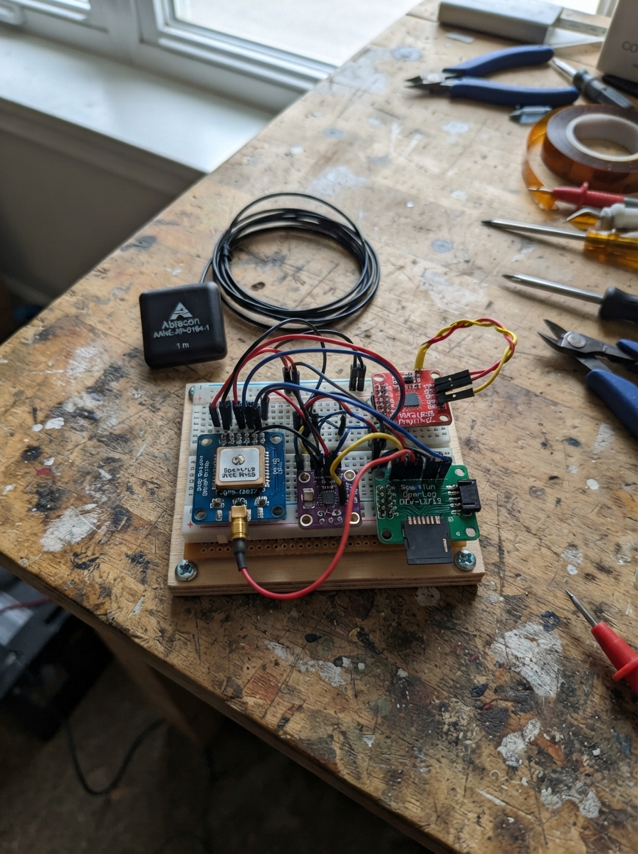
This project builds a high-altitude balloon tracker that records GPS position, atmospheric pressure, and temperature data throughout a stratospheric flight. The Raspberry Pi Pico collects readings from a u-blox MAX-M10S GNSS receiver, MS5611 barometric sensor, and K-type thermocouple amplifier, then logs everything to an SD card via the SparkFun OpenLog module for later analysis.
The guide provides a complete wiring diagram, parts list, and Arduino firmware that auto-detects the GPS baud rate and mirrors sensor data to both USB and the data logger. Assembly steps cover sensor calibration, pre-flight testing, and antenna positioning, ensuring reliable data collection from launch through descent.
Wiring diagram
Gather all the parts
Assemble it in 9 steps
1. Choose the specified modules
Use a Raspberry Pi Pico 2, a SparkFun GPS-18037 MAX-M10S breakout and Abracon AANE-AP-0164-1 active SMA antenna, a GY-63 MS5611 board with onboard I2C pull-ups, an Adafruit MAX31855 breakout, and an ungrounded K-type probe rated for -80 C or colder. Do not use a bare GNSS chip.
2. Wire power with USB disconnected
With USB disconnected, connect GPS 3.3V to Pico 3V3 and GPS GND to GND. Pressure and thermocouple VCC also go to 3V3. Never connect the GPS power or signals to 5 V or VBUS. The active antenna receives power through its SMA cable, not separate power wires.
3. Connect GPS and pressure
GPS TX goes to GP1 (received position data); RX goes to GP0 (configuration commands). Pressure SDA goes to GP4 (data), SCL to GP5 (clock), PS to 3V3 (I2C mode), and CSB to GND (address 0x77). Leave SDO disconnected.
4. Connect the cold-air probe
MAX31855 SCK goes to GP18 (clock), CS to GP17 (select), and SO to GP16 (temperature data). Connect probe positive to T+ and negative to T-. Follow the probe's polarity marking, not assumed wire colours.
- The probe junction must not touch circuit ground; a grounded probe causes a fault.
5. Test before designing a flight payload
Keep electronics in a vented insulated enclosure; expose only the probe to outside air, shielded from direct sunlight and payload heat. Keep the GPS antenna facing the sky. The pressure port needs outside air and must not be sealed or blocked. USB output is one CSV row per second at 115200 baud. A nan value means missing or invalid data.
- This is a USB bench prototype, not a launch-ready tracker: it has no battery design or recovery radio.
- MS5611 is rated for 10–1200 hPa: below 10 hPa, roughly above 31 km, its readings are out of range. Use GPS altitude, not a sea-level pressure formula, at stratospheric heights.
- The electronics must remain within their rated temperature ranges; the MS5611 minimum is -40 C. Insulation alone is not proof of adequate thermal control. Cold and low-pressure testing are required.
- Do not launch until flight power, thermal control, verified logging, recovery tracking, and local aviation requirements are addressed.
6. Add the serial OpenLog
Use the standard SparkFun OpenLog DEV-13712 (or DEV-13955 with headers), not Qwiic OpenLog or OpenLog Artemis. With USB disconnected, wire VCC to 3V3, GND to GND, RXI to GP8 (data from Pico), and TXO to GP9 (ready signal to Pico). Leave DTR unconnected. Existing sensor wires stay unchanged.
7. Prepare the memory card
Insert a 4–32 GB microSD card formatted FAT32 while power is off. Keep OpenLog at its factory 9600 baud and New Log mode (mode 0). It creates a LOGxxxxx.TXT file each time it starts. Each file contains comma-separated columns that a spreadsheet can import. The card fits inside the OpenLog socket; it needs no separate wires.
- Do not use an exFAT-formatted card. A missing or failed card prevents onboard logging, but USB output continues after the 15-second startup timeout.
8. Verify a recording before flight
Power the complete setup together. Check the USB startup message says OpenLog READY, then record for several minutes. Disconnect power before removing the card and open the newest LOG file on your computer. Verify one row per second with the same columns as USB. Repeat for longer than the flight and at expected enclosure temperatures.
- READY confirms startup only, not later successful writes. This firmware cannot detect a full card or all card write failures. Sudden power loss can lose buffered readings or corrupt a file. Never remove the card while powered.
- OpenLog adds around 20–23 mA while writing according to SparkFun; card-dependent peaks vary. Measure the complete setup before final battery sizing. Secure the card and all wiring against vibration.
9. Attach and position the active GNSS antenna
Connect the AANE-AP-0164-1 antenna SMA plug directly to the GPS-18037 SMA socket and tighten finger-tight. No adapter or separate antenna power wires are needed. Mount the patch antenna facing the sky, away from foil insulation, batteries and metal. Secure the cable so it cannot pull on the connector. Leave GPS SDA, SCL and unused control pins disconnected. Firmware tries 38400 baud first, then other common rates, and requests Airborne 4g mode at startup. Check GPS airborne configuration OK and valid positions outdoors, then inspect the OpenLog file.
- GPS-18037 requires 3.3 V, not 5 V. Remove the former ELT0169 VBUS connection before powering on.
- Allow up to 25 mA extra for the active antenna. Measure complete payload consumption before battery sizing.
- Keep receiver electronics within their temperature ratings. Cold and endurance tests are required before flight.
- GPS-18037 and Abracon AANE-AP-0164-1 are manual shopping-list entries; match these exact models. The antenna has a 1 m cable and SMA male connector. Its operating range is -40 to +85 C; ensure it stays within that range. Manufacturer RF measurements use a 70 x 70 mm ground plane; test reception in the finished payload.
Review all connections
1. Connections between "gps" and "Raspberry Pi Pico"
2. Connections between "antenna" and "Raspberry Pi Pico"
3. Connections between "pressure" and "Raspberry Pi Pico"
4. Connections between "thermo" and "Raspberry Pi Pico"
5. Connections between "probe" and "Raspberry Pi Pico"
6. Connections between "logger" and "Raspberry Pi Pico"
Deploy the firmware
#include <Arduino.h>
#include <Wire.h>
#include <SPI.h>
#include <SparkFun_u-blox_GNSS_v3.h>
#include <MS5611.h>
#include <Adafruit_MAX31855.h>

SFE_UBLOX_GNSS_SERIAL gps;
MS5611 barometer(0x77);
Adafruit_MAX31855 thermocouple(18, 17, 16);
auto &logSerial = Serial2;
bool loggerReady=false;

// Write each identical row to USB and the external logger.
class MirroredOutput : public Print {
public:
  using Print::write;
  size_t write(uint8_t c) override {
    Serial.write(c);
    if(loggerReady) logSerial.write(c);
    return 1;
  }
} output;

bool gpsReady=false, pressureReady=false, thermoReady=false;
uint32_t lastSample=0;
uint32_t gpsBaud=0;
void setup() {
  Serial.begin(115200);
  logSerial.setTX(8);
  logSerial.setRX(9);
  logSerial.begin(9600);
  // OpenLog sends < only after its card and log file are ready.
  uint32_t bootStart=millis();
  while(millis()-bootStart < 15000) {
    if(logSerial.available() && logSerial.read()=='<') { loggerReady=true; break; }
    delay(1);
  }
  Wire.setSDA(4);
  Wire.setSCL(5);
  Wire.begin();
  Serial1.setTX(0);
  Serial1.setRX(1);
  Serial1.begin(38400);
  delay(1000);
  pressureReady=barometer.begin();
  thermoReady=thermocouple.begin();
  // SparkFun GPS-18037 MAX-M10S UART: detect a valid UBX reply, not readable text alone.
  const uint32_t rates[] = {38400, 9600, 19200, 57600, 115200};
  for (uint32_t rate : rates) {
    Serial1.end();
    Serial1.begin(rate);
    delay(150);
    while (Serial1.available()) Serial1.read();
    if (gps.begin(Serial1)) {
      gpsReady=true;
      gpsBaud=rate;
      break;
    }
  }
  if(gpsReady) gpsReady=gps.setDynamicModel(DYN_MODEL_AIRBORNE4g);
  Serial.print("# OpenLog startup: "); Serial.println(loggerReady ? "READY (not a write verification)" : "FAILED; USB only, power-cycle to retry");
  output.println("# Balloon sensor logger; elapsed milliseconds restart on Pico reset");
  output.print("# GPS detected baud (0 means no response): "); output.println(gpsBaud);
  output.print("# GPS airborne configuration: "); output.println(gpsReady ? "OK" : "FAILED");
  output.print("# Pressure sensor: "); output.println(pressureReady ? "OK" : "FAILED");
  output.println("ms,gps_ok,latitude_deg,longitude_deg,gps_altitude_m,pressure_hPa,pressure_in_range,air_C,electronics_C");
}
void loop() {
  if(gpsReady) gps.checkUblox();
  if(millis()-lastSample<1000) return;
  lastSample=millis();
  bool fix=false;
  if(gpsReady && gps.getPVT(100)) fix=gps.getGnssFixOk();
  float p=NAN, internal=NAN;
  if(pressureReady && barometer.read()==0) {
    p=barometer.getPressure(); internal=barometer.getTemperature();
  }
  double air=thermoReady ? thermocouple.readCelsius() : NAN;
  output.print(lastSample); output.print(','); output.print(fix); output.print(',');
  if(fix) output.print(gps.getLatitude()/1e7,7); else output.print("nan");
  output.print(',');
  if(fix) output.print(gps.getLongitude()/1e7,7); else output.print("nan");
  output.print(',');
  if(fix) output.print(gps.getAltitude()/1000.0,2); else output.print("nan");
  output.print(','); output.print(p,3); output.print(','); output.print(!isnan(p) && p>=10 && p<=1200);
  output.print(','); output.print(air,2); output.print(','); output.println(internal,2);
}
Remix this project
Make it yours in one click
Open a full copy of this project in your own Schematik workspace, diagram, code, parts, and assembly steps included. Swap the sensor, add features, or redesign the whole thing with AI. The author's original stays untouched.
Related projects
ESP32 Project Ideas (copy) (copy)
Raspberry Pi Pico · November 11, 2026Lucas Soares
Spotify Lyrics Display
Raspberry Pi Pico · November 5, 2026wilber26susan
Portable AX.25 Radio TNC
Raspberry Pi Pico · November 5, 2026Kelvin J. HIll