Community project
Custom Macro Control Pad
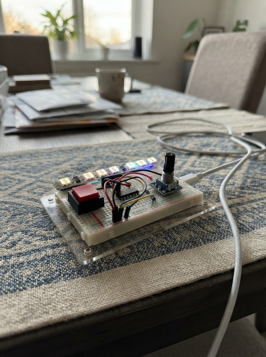
Build a programmable macro control pad with six customizable buttons, a rotary encoder, and addressable RGB feedback. This ESP32-based device appears as a USB HID keyboard to any computer, letting you trigger complex key sequences, mouse commands, and media controls with a single press. The rotary encoder switches between three modes (zoom, volume, pan) with visual feedback from the addressable LED strip.
This guide provides a complete wiring diagram, parts list, and ready-to-customize firmware. Assembly covers preparing the button matrix, safely interfacing the 5V LED strip to the 3.3V ESP32 using a level shifter, and configuring the encoder. Edit the macro definitions in the firmware to suit your favorite applications, then verify all connections before powering up via USB.
Wiring diagram

Gather all the parts
Assemble it in 5 steps
1. Prepare a common ground and the six key switches
Mount the six normally-open momentary switches. Connect one terminal of every switch to the ESP32-S2 Mini GND rail. Connect each other switch terminal respectively to GPIO1 through GPIO6: key 1→GPIO1, key 2→GPIO2, key 3→GPIO3, key 4→GPIO4, key 5→GPIO5, key 6→GPIO6. No external pull-up resistors are needed because the firmware enables the ESP32 internal pull-ups.
- On four-pin tactile switches, use terminals from opposite sides of the switch; terminals on the same side are already connected.
- Keep the key order consistent with the physical panel because the LEDs and macros are numbered in this order.
- Do not connect any switch signal terminal to 3.3 V or 5 V; each signal goes only to its assigned GPIO and is pulled to ground when pressed.
2. Wire the encoder at 3.3 V
Connect encoder VCC to the board 3V3 rail and encoder GND to GND. Connect CLK to GPIO7, DT to GPIO8, and SW to GPIO9. The encoder push switch changes mode: zoom, volume, then horizontal pan.
- If rotation feels reversed, swap only the CLK and DT wires, or reverse the direction test in firmware.
- Use a short ground wire and keep the encoder wires together to reduce bounce/noise.
- Power the KY-040-style encoder module from 3.3 V, not 5 V, so CLK, DT, and SW never output unsafe 5 V levels to the ESP32.
3. Build the protected 5 V LED data path
Connect GPIO10 to 1A on the 74AHCT125. Connect the AHCT125 VCC to the board 5V rail and GND to GND. Tie 1OE to GND to permanently enable that buffer. Connect 1Y to one end of the 330 Ω resistor, then connect the other resistor end to DIN of the first WS2812B LED.
- Place the 330 Ω resistor physically close to the first LED DIN connection.
- A 74AHCT125 in a breadboard is oriented by its notch/dot; verify the actual pin numbers against its package marking before wiring pins named 1A, 1Y, 1OE, VCC, and GND.
- Do not connect GPIO10 directly to a 5 V WS2812 DIN. The AHCT125 is required to translate the 3.3 V ESP32 signal to dependable 5 V logic.
- Use an AHCT/HCT buffer, not a generic BSS138 bidirectional level-shifter module: those modules are too slow/unreliable for WS2812 data.
4. Power and arrange the six key LEDs
Daisy-chain the six WS2812B LEDs in key order: DOUT of LED 1 to DIN of LED 2, continuing through LED 6. Connect the first LED chain 5V pad to the board 5V rail and every LED GND pad to the common GND rail. Mount one LED beneath each key. Leave the final DOUT disconnected.
- Follow the arrows or DIN/DOUT labels printed on the LED strip/PCBs; data enters only at DIN.
- The firmware caps brightness at 32/255 to limit the six LEDs to a USB-friendly current level.
- Never power the WS2812 LEDs from the ESP32 3V3 pin.
- Disconnect USB while altering wiring. A reversed 5 V/GND LED connection can damage the LEDs and USB port.
5. Check before connecting USB
Inspect for one shared ground among board, keys, encoder, AHCT125, and LEDs. Confirm no LED 5 V wire reaches any ESP32 GPIO. Then connect the ESP32-S2 Mini to the computer by USB and use Schematik’s Deploy button to flash the firmware.
- At startup all LEDs indicate the current encoder mode; the brighter position identifies zoom (key 1), volume (key 2), or pan (key 3).
- The default six macros are Copy, Paste, Undo, Redo, Save, and Find; edit the clearly marked sendMacro() function later to customize them.
- Use a data-capable USB cable; a charge-only cable cannot provide USB keyboard/mouse operation.
Review all connections
1. Connections between "key_1" and "ESP32"
2. Connections between "key_2" and "ESP32"
3. Connections between "key_3" and "ESP32"
4. Connections between "key_4" and "ESP32"
5. Connections between "key_5" and "ESP32"
6. Connections between "key_6" and "ESP32"
7. Connections between "encoder_1" and "ESP32"
8. Connections between "led_level_shifter" and "ESP32"
9. Connections between "led_data_resistor" and "ESP32"
10. Connections between "key_leds" and "ESP32"
Deploy the firmware
#include <Arduino.h>
#include <USB.h>
#include <USBHIDKeyboard.h>
#include <USBHIDMouse.h>
#include <USBHIDConsumerControl.h>
#include <Adafruit_NeoPixel.h>

// Edit these six actions to suit your software. The board appears as a USB HID device.

// Hoisted type definitions
enum EncoderMode : uint8_t { ZOOM_MODE, VOLUME_MODE, PAN_MODE };


// Forward declarations
void updateLighting();
void sendMacro(uint8_t keyIndex);
void handleEncoderStep(int8_t direction);
void pollKeys();
void pollEncoderButton();
void pollEncoder();

constexpr uint8_t KEY_PINS[] = {1, 2, 3, 4, 5, 6};
constexpr uint8_t KEY_COUNT = sizeof(KEY_PINS) / sizeof(KEY_PINS[0]);
constexpr uint8_t ENC_CLK_PIN = 7;
constexpr uint8_t ENC_DT_PIN = 8;
constexpr uint8_t ENC_SW_PIN = 9;
constexpr uint8_t LED_DATA_PIN = 10;
constexpr uint8_t LED_COUNT = 6;
constexpr uint8_t LED_BRIGHTNESS = 32;  // About 13% maximum; USB-friendly.
constexpr uint16_t DEBOUNCE_MS = 20;

USBHIDKeyboard Keyboard;
USBHIDMouse Mouse;
USBHIDConsumerControl ConsumerControl;
Adafruit_NeoPixel pixels(LED_COUNT, LED_DATA_PIN, NEO_GRB + NEO_KHZ800);


EncoderMode encoderMode = ZOOM_MODE;

bool keyStable[KEY_COUNT];
bool keyLastRaw[KEY_COUNT];
uint32_t keyChangedAt[KEY_COUNT];
bool encoderButtonStable;
bool encoderButtonLastRaw;
uint32_t encoderButtonChangedAt = 0;
uint8_t lastEncoderCLK;

const uint32_t modeColors[] = {
  Adafruit_NeoPixel::Color(0, 40, 100), // blue: zoom
  Adafruit_NeoPixel::Color(0, 100, 20), // green: volume
  Adafruit_NeoPixel::Color(100, 35, 0)  // orange: pan
};

void updateLighting() {
  for (uint8_t i = 0; i < LED_COUNT; ++i) {
    pixels.setPixelColor(i, modeColors[encoderMode]);
  }
  // A brighter LED marks the current mode: key 1 zoom, key 2 volume, key 3 pan.
  pixels.setPixelColor(static_cast<uint8_t>(encoderMode),
                       Adafruit_NeoPixel::Color(120, 120, 120));
  pixels.show();
}

void sendMacro(uint8_t keyIndex) {
  // Default macros: Ctrl+C, Ctrl+V, Ctrl+Z, Ctrl+Shift+Z, Ctrl+S, Ctrl+F.
  // Change this function to program the six keys for your own applications.
  switch (keyIndex) {
    case 0:
      Keyboard.press(KEY_LEFT_CTRL); Keyboard.write('c'); Keyboard.releaseAll(); break;
    case 1:
      Keyboard.press(KEY_LEFT_CTRL); Keyboard.write('v'); Keyboard.releaseAll(); break;
    case 2:
      Keyboard.press(KEY_LEFT_CTRL); Keyboard.write('z'); Keyboard.releaseAll(); break;
    case 3:
      Keyboard.press(KEY_LEFT_CTRL); Keyboard.press(KEY_LEFT_SHIFT); Keyboard.write('z'); Keyboard.releaseAll(); break;
    case 4:
      Keyboard.press(KEY_LEFT_CTRL); Keyboard.write('s'); Keyboard.releaseAll(); break;
    case 5:
      Keyboard.press(KEY_LEFT_CTRL); Keyboard.write('f'); Keyboard.releaseAll(); break;
  }
}

void handleEncoderStep(int8_t direction) {
  if (encoderMode == ZOOM_MODE) {
    // Ctrl + mouse wheel is zoom in most desktop applications and browsers.
    Keyboard.press(KEY_LEFT_CTRL);
    Mouse.move(0, 0, direction);
    Keyboard.releaseAll();
  } else if (encoderMode == VOLUME_MODE) {
    ConsumerControl.write(direction > 0 ? CONSUMER_CONTROL_VOLUME_INCREMENT
                                        : CONSUMER_CONTROL_VOLUME_DECREMENT);
  } else {
    // Horizontal scroll / pan. Application support varies.
    Mouse.move(0, 0, 0, direction);
  }
}

void pollKeys() {
  const uint32_t now = millis();
  for (uint8_t i = 0; i < KEY_COUNT; ++i) {
    const bool raw = digitalRead(KEY_PINS[i]);
    if (raw != keyLastRaw[i]) {
      keyLastRaw[i] = raw;
      keyChangedAt[i] = now;
    }
    if ((now - keyChangedAt[i] >= DEBOUNCE_MS) && raw != keyStable[i]) {
      keyStable[i] = raw;
      if (keyStable[i] == LOW) sendMacro(i);
    }
  }
}

void pollEncoderButton() {
  const uint32_t now = millis();
  const bool raw = digitalRead(ENC_SW_PIN);
  if (raw != encoderButtonLastRaw) {
    encoderButtonLastRaw = raw;
    encoderButtonChangedAt = now;
  }
  if ((now - encoderButtonChangedAt >= DEBOUNCE_MS) && raw != encoderButtonStable) {
    encoderButtonStable = raw;
    if (encoderButtonStable == LOW) {
      encoderMode = static_cast<EncoderMode>((encoderMode + 1) % 3);
      updateLighting();
    }
  }
}

void pollEncoder() {
  const uint8_t clk = digitalRead(ENC_CLK_PIN);
  if (clk != lastEncoderCLK && clk == HIGH) {
    const int8_t direction = (digitalRead(ENC_DT_PIN) != clk) ? 1 : -1;
    handleEncoderStep(direction);
  }
  lastEncoderCLK = clk;
}

void setup() {
  for (uint8_t i = 0; i < KEY_COUNT; ++i) {
    pinMode(KEY_PINS[i], INPUT_PULLUP);
    keyStable[i] = keyLastRaw[i] = digitalRead(KEY_PINS[i]);
    keyChangedAt[i] = millis();
  }
  pinMode(ENC_CLK_PIN, INPUT_PULLUP);
  pinMode(ENC_DT_PIN, INPUT_PULLUP);
  pinMode(ENC_SW_PIN, INPUT_PULLUP);
  lastEncoderCLK = digitalRead(ENC_CLK_PIN);
  encoderButtonStable = encoderButtonLastRaw = digitalRead(ENC_SW_PIN);

  pixels.begin();
  pixels.setBrightness(LED_BRIGHTNESS);
  updateLighting();

  Keyboard.begin();
  Mouse.begin();
  ConsumerControl.begin();
  USB.begin();
}

void loop() {
  pollKeys();
  pollEncoderButton();
  pollEncoder();
}
Remix this project
Make it yours in one click
Open a full copy of this project in your own Schematik workspace — diagram, code, parts, and assembly steps included. Swap the sensor, add features, or redesign the whole thing with AI. The author's original stays untouched.