Community project
Desktop AI Assistant Robot
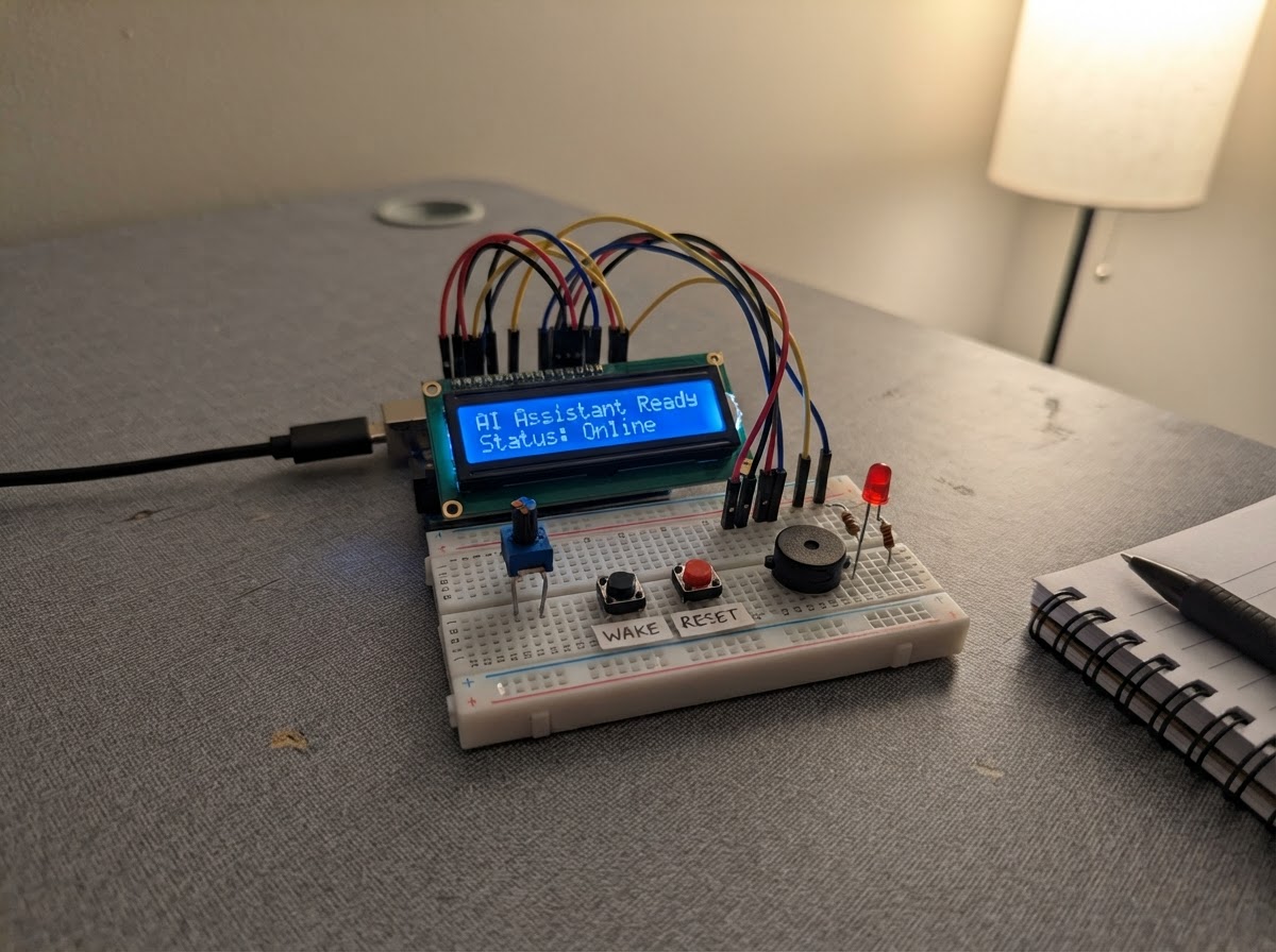
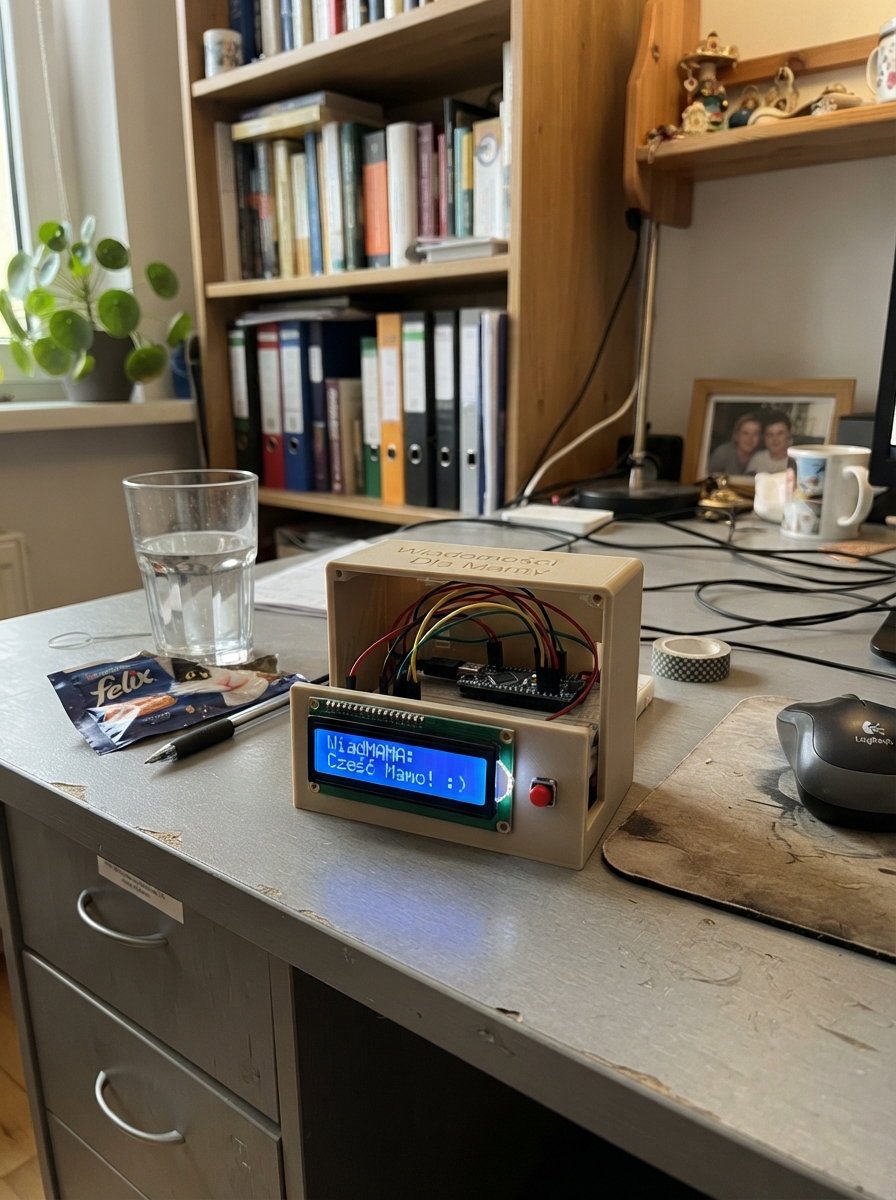
This desktop AI assistant robot brings conversational intelligence to your workbench with a friendly LCD face, tactile controls, and visual feedback. Built around an Arduino Uno, the project combines a 16x2 display, three navigation buttons, status LEDs, and a buzzer to create an interactive interface that responds to commands from a connected computer.
The guide provides a complete wiring diagram, parts list, and step-by-step assembly instructions for constructing the robot's enclosure and breadboard layout. Included firmware handles button debouncing, serial communication with a host system, and display management, giving makers a solid foundation to expand with their own AI backend or custom logic.
Wiring diagram

Gather all the parts
Assemble it in 6 steps
1. Print the two enclosure pieces
Open `data/ai_assistant_enclosure.scad`, export it once with `part_to_export` set to `FRONT_BODY` and once set to `REAR_COVER`, then print both pieces in PLA or PETG. Before printing, measure your LCD circuit board and breadboard with a ruler or calipers and adjust the clearly named size values at the top if yours differs. Print the front with its smooth face on the build plate and the cover with its smooth outside on the build plate; neither part needs support material.
- Use 0.20 mm layers, 3 or 4 wall loops, and 15–20% gyroid infill for a strong, neat case.
- The design is 190 × 125 × 58 mm, which fits comfortably on the P1S plate.
- Do not force an LCD through a too-small opening — change the editable LCD measurements first, because forcing it can crack the screen or its circuit board.
2. Prepare the breadboard power rails
Place the breadboard in its long internal bay temporarily. Run one jumper from the Uno 5V pin to the breadboard positive rail (power), and one jumper from any Uno GND pin to the breadboard negative rail (ground). Keep the left side of the Uno facing the case USB opening.
- Use red for 5V and black for GND so every later connection is easier to trace.
- Do not install the rear cover yet; all wiring must remain reachable.
- Do not connect the Uno 5V rail to VIN — VIN expects a higher external supply, while the LCD and breadboard use regulated 5V.
3. Install the LCD face and contrast knob
Place the LCD behind the front window with its screen facing outward. Hold it against the four printed posts; use M3 screws only if you already own suitable screws, otherwise secure the PCB rear edge to the posts with a small piece of foam tape so it cannot move. Connect LCD VCC to 5V (power), GND to GND (ground), RS to Uno D12 (data), EN to D11 (data), D4 to D10 (data), D5 to D9 (data), D6 to D8 (data), D7 to D7 (data), and RW to GND (ground). Connect the LCD LED+ pin through the separate 220 Ω resistor to 5V (backlight power), then connect LCD LED− to GND (ground). Connect one outer leg of the 10 kΩ potentiometer to 5V (power), its other outer leg to GND (ground), and its centre leg to LCD VO (contrast signal).
- Turn the small 10 kΩ knob after power-up until dark letters become visible.
- The LCD’s pins are normally numbered from the end marked pin 1; follow the labels printed on its circuit board, not wire position alone.
- Make sure VCC and GND are not swapped — swapped power can damage the LCD.
- The LCD backlight needs its 220 Ω resistor; connecting LED+ straight to 5V can shorten the backlight’s life.
4. Fit the buttons, lights, and buzzer
Push the three buttons into the lower front holes, then connect one leg of each button to GND (ground). Connect the remaining legs to D2 for Previous (signal), D3 for Action (signal), and D4 for Next (signal). Put the green, blue, and red LEDs into the three small holes with their long legs facing inward. Connect each long leg through its own 220 Ω resistor to D6 for green Ready (signal), D13 for blue Listen (signal), and A4 for red Alert (signal); connect each short LED leg to GND (ground). Place the buzzer behind its grille, then connect its signal pin to D5 (signal) and its other pin to GND (ground).
- The buttons use the Uno’s built-in pull-up setting, so a press works by joining the signal leg to ground.
- For every LED, the longer leg is positive and must go through its own resistor.
- Do not put an LED directly between an Uno pin and ground — the resistor protects both the LED and the Uno pin.
- If a LED does not light, disconnect USB power first and turn that LED around; LEDs only work in one direction.
5. Mount the Uno and arrange the wiring
Press the Uno gently into the four printed retaining clips in the left internal bay, with its USB socket lined up with the side opening. Place the breadboard in the large bay and arrange wires in low bundles along the printed channels so the rear cover will not pinch them. Leave enough slack for the LCD wires but keep them away from the USB opening.
- Test-fit the rear cover without snapping it fully closed; if it touches a wire, reroute that wire in the channel rather than forcing the cover.
- The Uno USB cable is both the power connection and the link to your laptop AI software.
- Do not force the Uno into a clip if it is misaligned — pushing on the USB socket or headers can damage the board.
6. Close the assistant and test it
With the USB cable unplugged, align the rear cover’s locating lip with the rear opening and press evenly around all four latch positions until it clicks into place. Use the finger notch to remove it later for maintenance. Plug the Uno into the laptop through the side opening, then press Schematik’s Deploy button to load the assistant firmware.
- The face starts as “AI ASSISTANT / Ready.” The laptop can send `FACE:hello|how can I help?`, `LED:0` through `LED:7`, or `BEEP` followed by a new line over USB serial.
- A button press sends `BUTTON:PREV`, `BUTTON:ACTION`, or `BUTTON:NEXT` back to your laptop AI program.
- If the rear cover will not seat evenly, stop and inspect for trapped wires; forcing it can cut jumper insulation or crack the printed latch.
Review all connections
1. Connections between "breadboard_1" and "Arduino"
2. Connections between "lcd1602_1" and "Arduino"
3. Connections between "contrast_pot_1" and "Arduino"
4. Connections between "res_lcd_backlight" and "Arduino"
5. Connections between "button_prev" and "Arduino"
6. Connections between "button_action" and "Arduino"
7. Connections between "button_next" and "Arduino"
8. Connections between "buzzer_1" and "Arduino"
9. Connections between "res_ready" and "Arduino"
10. Connections between "led_ready" and "Arduino"
11. Connections between "res_listen" and "Arduino"
12. Connections between "led_listen" and "Arduino"
13. Connections between "res_alert" and "Arduino"
14. Connections between "led_alert" and "Arduino"
Deploy the firmware
#include <Arduino.h>
#include <LiquidCrystal.h>


// Hoisted type definitions
struct Button {
  uint8_t pin;
  const char *name;
  bool stableState;
  bool lastReading;
  unsigned long lastChange;
};


// Forward declarations
void showFace();
void copyDisplayText(char *destination, const char *source);
void setLeds(uint8_t state);
void handleCommand(char *command);
void readLaptopCommands();
void readButtons();

const uint8_t BUTTON_PREV = 2;
const uint8_t BUTTON_ACTION = 3;
const uint8_t BUTTON_NEXT = 4;
const uint8_t BUZZER_PIN = 5;
const uint8_t LED_READY = 6;
const uint8_t LCD_D7 = 7;
const uint8_t LCD_D6 = 8;
const uint8_t LCD_D5 = 9;
const uint8_t LCD_D4 = 10;
const uint8_t LCD_EN = 11;
const uint8_t LCD_RS = 12;
const uint8_t LED_LISTEN = 13;
const uint8_t LED_ALERT = A4;

LiquidCrystal lcd(LCD_RS, LCD_EN, LCD_D4, LCD_D5, LCD_D6, LCD_D7);


Button buttons[] = {
  {BUTTON_PREV, "PREV", HIGH, HIGH, 0},
  {BUTTON_ACTION, "ACTION", HIGH, HIGH, 0},
  {BUTTON_NEXT, "NEXT", HIGH, HIGH, 0}
};
const uint8_t BUTTON_COUNT = sizeof(buttons) / sizeof(buttons[0]);
const unsigned long DEBOUNCE_MS = 35;

char line1[17] = "AI ASSISTANT";
char line2[17] = "Ready";
char serialBuffer[65];
uint8_t serialLength = 0;

void showFace() {
  lcd.setCursor(0, 0);
  lcd.print("                ");
  lcd.setCursor(0, 0);
  lcd.print(line1);
  lcd.setCursor(0, 1);
  lcd.print("                ");
  lcd.setCursor(0, 1);
  lcd.print(line2);
}

void copyDisplayText(char *destination, const char *source) {
  uint8_t i = 0;
  while (source[i] != '\0' && i < 16) {
    destination[i] = source[i];
    i++;
  }
  destination[i] = '\0';
}

void setLeds(uint8_t state) {
  digitalWrite(LED_READY, (state & 1) ? HIGH : LOW);
  digitalWrite(LED_LISTEN, (state & 2) ? HIGH : LOW);
  digitalWrite(LED_ALERT, (state & 4) ? HIGH : LOW);
}

void handleCommand(char *command) {
  if (strncmp(command, "FACE:", 5) == 0) {
    char *separator = strchr(command + 5, '|');
    if (separator != NULL) {
      *separator = '\0';
      copyDisplayText(line1, command + 5);
      copyDisplayText(line2, separator + 1);
    } else {
      copyDisplayText(line1, command + 5);
      line2[0] = '\0';
    }
    showFace();
    Serial.println(F("OK FACE"));
  } else if (strncmp(command, "LED:", 4) == 0) {
    int state = atoi(command + 4);
    if (state >= 0 && state <= 7) {
      setLeds((uint8_t)state);
      Serial.println(F("OK LED"));
    }
  } else if (strncmp(command, "BEEP", 4) == 0) {
    tone(BUZZER_PIN, 1600, 90);
    Serial.println(F("OK BEEP"));
  } else if (strncmp(command, "PING", 4) == 0) {
    Serial.println(F("PONG"));
  }
}

void readLaptopCommands() {
  while (Serial.available() > 0) {
    char incoming = (char)Serial.read();
    if (incoming == '\r') continue;
    if (incoming == '\n') {
      serialBuffer[serialLength] = '\0';
      if (serialLength > 0) handleCommand(serialBuffer);
      serialLength = 0;
    } else if (serialLength < sizeof(serialBuffer) - 1) {
      serialBuffer[serialLength++] = incoming;
    } else {
      serialLength = 0;
    }
  }
}

void readButtons() {
  unsigned long now = millis();
  for (uint8_t i = 0; i < BUTTON_COUNT; i++) {
    bool reading = digitalRead(buttons[i].pin);
    if (reading != buttons[i].lastReading) {
      buttons[i].lastChange = now;
      buttons[i].lastReading = reading;
    }
    if ((now - buttons[i].lastChange) >= DEBOUNCE_MS && reading != buttons[i].stableState) {
      buttons[i].stableState = reading;
      if (buttons[i].stableState == LOW) {
        Serial.print(F("BUTTON:"));
        Serial.println(buttons[i].name);
        tone(BUZZER_PIN, 1100, 35);
      }
    }
  }
}

void setup() {
  pinMode(BUZZER_PIN, OUTPUT);
  pinMode(LED_READY, OUTPUT);
  pinMode(LED_LISTEN, OUTPUT);
  pinMode(LED_ALERT, OUTPUT);
  for (uint8_t i = 0; i < BUTTON_COUNT; i++) pinMode(buttons[i].pin, INPUT_PULLUP);
  setLeds(1);
  Serial.begin(115200);
  lcd.begin(16, 2);
  showFace();
  Serial.println(F("AI_ASSISTANT_READY"));
}

void loop() {
  readLaptopCommands();
  readButtons();
}
Remix this project
Make it yours in one click
Open a full copy of this project in your own Schematik workspace — diagram, code, parts, and assembly steps included. Swap the sensor, add features, or redesign the whole thing with AI. The author's original stays untouched.