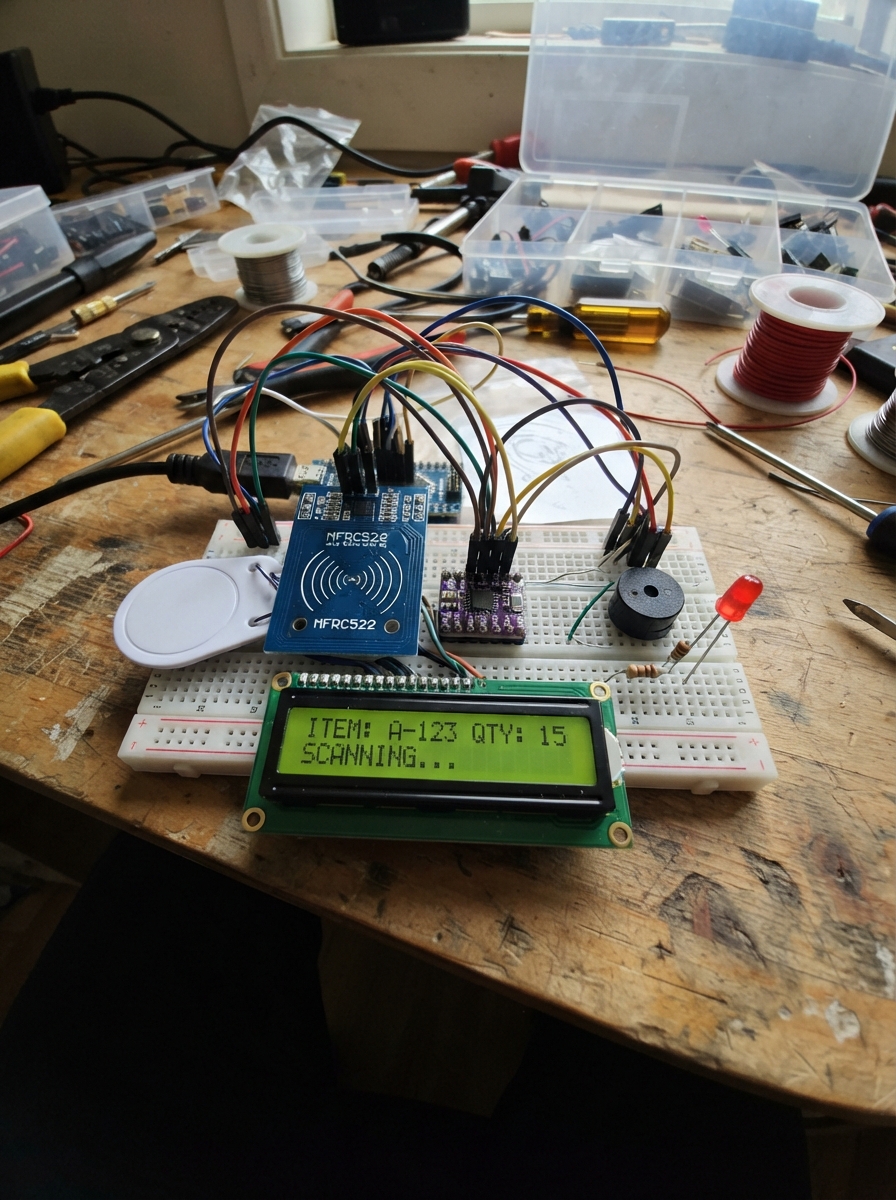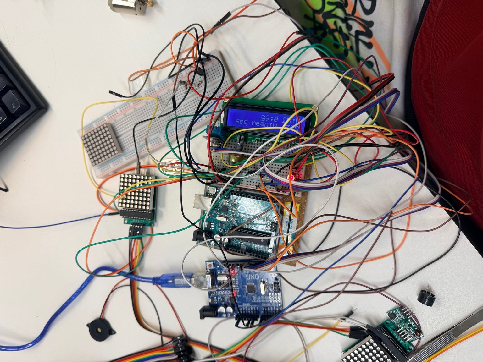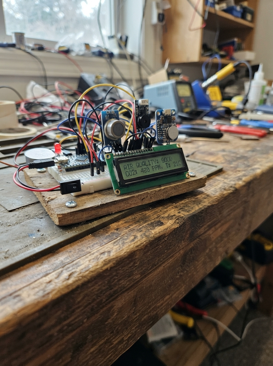
This smart classroom air monitor combines sound and air quality sensing to track environmental conditions in real time. Built around an Arduino Uno, the system reads noise levels from a KY-038 sound sensor and air quality data from an MQ135 sensor, displaying results on a 16x2 LCD screen with visual and audible alerts via LEDs and a piezo buzzer. A precision RTC module timestamps all readings for logging and analysis.
The guide provides a complete wiring diagram, full parts list, calibrated firmware, and step-by-step assembly instructions. Builders will learn how to integrate multiple I2C sensors, handle sensor warmup periods, manage display updates efficiently, and implement threshold-based alerting. The modular design makes it easy to customize thresholds and add additional sensors for expanded monitoring capabilities.
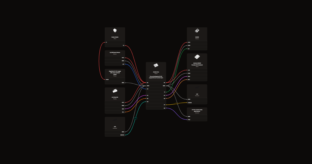
Wiring diagram
Gather all the parts
Assemble it in 5 steps
1. Arrange the board and modules
Use one full-size 830-point breadboard. Put the Uno to its left, microphone and MQ-135 along the top edge, LCD above the board and RTC at upper right. Use male-to-male and female-to-male jumpers as needed (about 25 leads). Keep the hot MQ-135 can exposed and away from fingers and plastic.
2. Wire power and signal junctions
The switched red rail feeds the Uno 5V header and GND to the blue rail. Use one continuous section or bridge split rails with matching jumpers. Feed sound, MQ-135 and LCD VCC and RTC VIN from red; tie their grounds to blue. Use yellow for sound AO to A0 and orange for MQ-135 AO (marked A0 on some modules) to A1. Leave both digital outputs open. Join Uno A4 and both SDA pins in strip A10–E10 (green wires); join A5 and both SCL pins in A12–E12 (purple wires). Read module labels; header order varies.
3. Place the LEDs diagonally
With numbered rows increasing left to right and A–E above the center gap, put green long leg in D24 and short leg in D25 (along the board). Put red long leg in E40 and short leg in F40 (across the center gap; gently spread leads). Connect D6 to A20; put green resistor between B20 and B24. Connect D7 to A36; put red resistor between B36 and B40. Ground green via A25 and red via J40. Each resistor is 220 ohms; each LED has legs in separate strips.
4. Connect the active buzzer
Put buzzer leads into two unused, separate strips (for example H48 and H51 if the lead spacing fits; otherwise use jumpers). Connect plus to D8 and minus to the ground rail.
- Use a self-oscillating 5 V piezo buzzer rated at 10 mA maximum. Do not connect an unknown-current or magnetic buzzer directly to D8.
5. Wire the rocker on the breadboard
With all power unplugged, bring the regulated supply positive to rocker T1 on a spare breadboard strip (for example A56). Bring T2 to a different strip (A58), then jumper that strip to the red rail. Connect supply negative to the blue rail. Use insulated terminal-to-jumper leads if the rocker tabs do not fit; secure the rocker next to the breadboard rather than forcing its tabs in. Verify polarity and 5.0 V at the switched rails before attaching the Uno and modules. The RTC backup cell may retain time when off.
- Only regulated 5.0 V DC may feed the Uno 5V header. Do not use VIN or wire mains to the breadboard.
- Before plugging in computer USB for Deploy, physically disconnect the external supply and disconnect the jumper between the Uno 5V header and red rail. Unplug USB before reconnecting them.
Review all connections
1. Connections between "sound" and "Arduino"
2. Connections between "air" and "Arduino"
3. Connections between "lcd" and "Arduino"
4. Connections between "rtc" and "Arduino"
5. Connections between "rg" and "Arduino"
6. Connections between "rr" and "Arduino"
7. Connections between "green" and "Arduino"
8. Connections between "red" and "Arduino"
9. Connections between "alarm" and "Arduino"
10. Connections between "supply" and "Arduino"
11. Connections between "rocker" and "Arduino"
Deploy the firmware
#include <Arduino.h>
#include <Wire.h>
#include <LiquidCrystal_I2C.h>
#include <RTClib.h>
#include <stdio.h>
#include <string.h>

// Starter values only. Calibrate on your own hardware (raw ADC counts).
constexpr uint16_t NOISE_THRESHOLD = 40, AIR_THRESHOLD = 500;
constexpr uint32_t AIR_WARMUP_MS = 180000, PAGE_MS = 3000;
constexpr uint8_t GREEN = 6, RED = 7, BUZZER = 8;
LiquidCrystal_I2C lcd(0x27,16,2), alternate(0x3F,16,2);
LiquidCrystal_I2C *screen = nullptr;
RTC_DS3231 rtc;
bool clockOk, noiseHigh, airHigh, airReady;
uint16_t lo=1023, hi=0, noise=0, air=0;
uint32_t started, windowAt, airAt, pageAt, refreshAt, logAt;
uint8_t page;
char previous[2][17] = {};

bool responds(uint8_t address) {
  Wire.beginTransmission(address);
  return Wire.endTransmission()==0;
}

// Overwrite only changed rows, padding old text away without flicker.
void line(uint8_t row, const char *text) {
  if (!screen) return;
  char padded[17];
  snprintf(padded,sizeof padded,"%-16.16s",text);
  if (strcmp(previous[row],padded)==0) return;
  strcpy(previous[row],padded);
  screen->setCursor(0,row);
  screen->print(padded);
}

void setup() {
  pinMode(GREEN,OUTPUT); pinMode(RED,OUTPUT); pinMode(BUZZER,OUTPUT);
  Serial.begin(115200);
  Wire.begin();
  clockOk=rtc.begin();
  // Set once on lost backup power; compile time is an approximate local time.
  if (clockOk) rtc.adjust(DateTime(2026, 11, 22, 04, 45, 0));
  if (responds(0x27)) screen=&lcd;
  else if (responds(0x3F)) screen=&alternate;
  if (screen) { screen->init(); screen->backlight(); }
  else Serial.println(F("LCD not found at 0x27 or 0x3F"));
  started=windowAt=airAt=pageAt=millis();
  air=analogRead(A1);
}

void loop() {
  uint32_t t=millis();
  // Peak-to-peak removes the microphone's DC offset. No delay between reads.
  analogRead(A0); // Allow the ADC input to settle after switching channels.
  uint16_t sample=analogRead(A0);
  if (sample<lo) lo=sample;
  if (sample>hi) hi=sample;
  if (t-windowAt>=50) {
    noise=hi-lo;
    noiseHigh=noise>NOISE_THRESHOLD;
    lo=1023; hi=0; windowAt=t;
  }
  if (t-airAt>=100) {
    analogRead(A1);
    air=(7UL*air+analogRead(A1)+4)/8;
    airAt=t;
  }
  if (t-started>=AIR_WARMUP_MS) airReady=true;
  airHigh=airReady && air>AIR_THRESHOLD;
  bool warning=noiseHigh || airHigh;
  digitalWrite(GREEN,airReady && !warning);
  digitalWrite(RED,warning);
  digitalWrite(BUZZER,warning);
  if (t-logAt>=500) {
    logAt=t;
    Serial.print(F("Noise p-p: ")); Serial.print(noise);
    Serial.print(F("  MQ-135: ")); Serial.print(air);
    if (!airReady) Serial.print(F(" (warming)"));
    Serial.println();
  }
  if (t-pageAt>=PAGE_MS) { page=(page+1)%4; pageAt=t; }
  if (t-refreshAt<150) return;
  refreshAt=t;
  char buf[24];
  switch (page) {
    case 0:
      snprintf(buf,sizeof buf,"Noise p-p: %u",noise); line(0,buf);
      line(1,noiseHigh?"HIGH NOISE":"Noise normal"); break;
    case 1:
      snprintf(buf,sizeof buf,"MQ-135 raw: %u",air); line(0,buf);
      line(1,!airReady?"Sensor warming":airHigh?"Air warning":"Air below limit"); break;
    case 2:
      if (clockOk) {
        DateTime d=rtc.now();
        snprintf(buf,sizeof buf,"Date %04u-%02u-%02u",d.year(),d.month(),d.day()); line(0,buf);
        snprintf(buf,sizeof buf,"Time %02u:%02u:%02u",d.hour(),d.minute(),d.second()); line(1,buf);
      } else { line(0,"RTC not found"); line(1,"Check SDA/SCL"); }
      break;
    default:
      line(0,noiseHigh && airHigh?"NOISE + AIR":noiseHigh?"HIGH NOISE":airHigh?"AIR QUALITY":"Classroom");
      line(1,warning?"WARNING":airReady?"Normal":"Air warming up");
  }
}
Remix this project
Make it yours in one click
Open a full copy of this project in your own Schematik workspace, diagram, code, parts, and assembly steps included. Swap the sensor, add features, or redesign the whole thing with AI. The author's original stays untouched.