Community project
Dual-Gate Speed Monitor
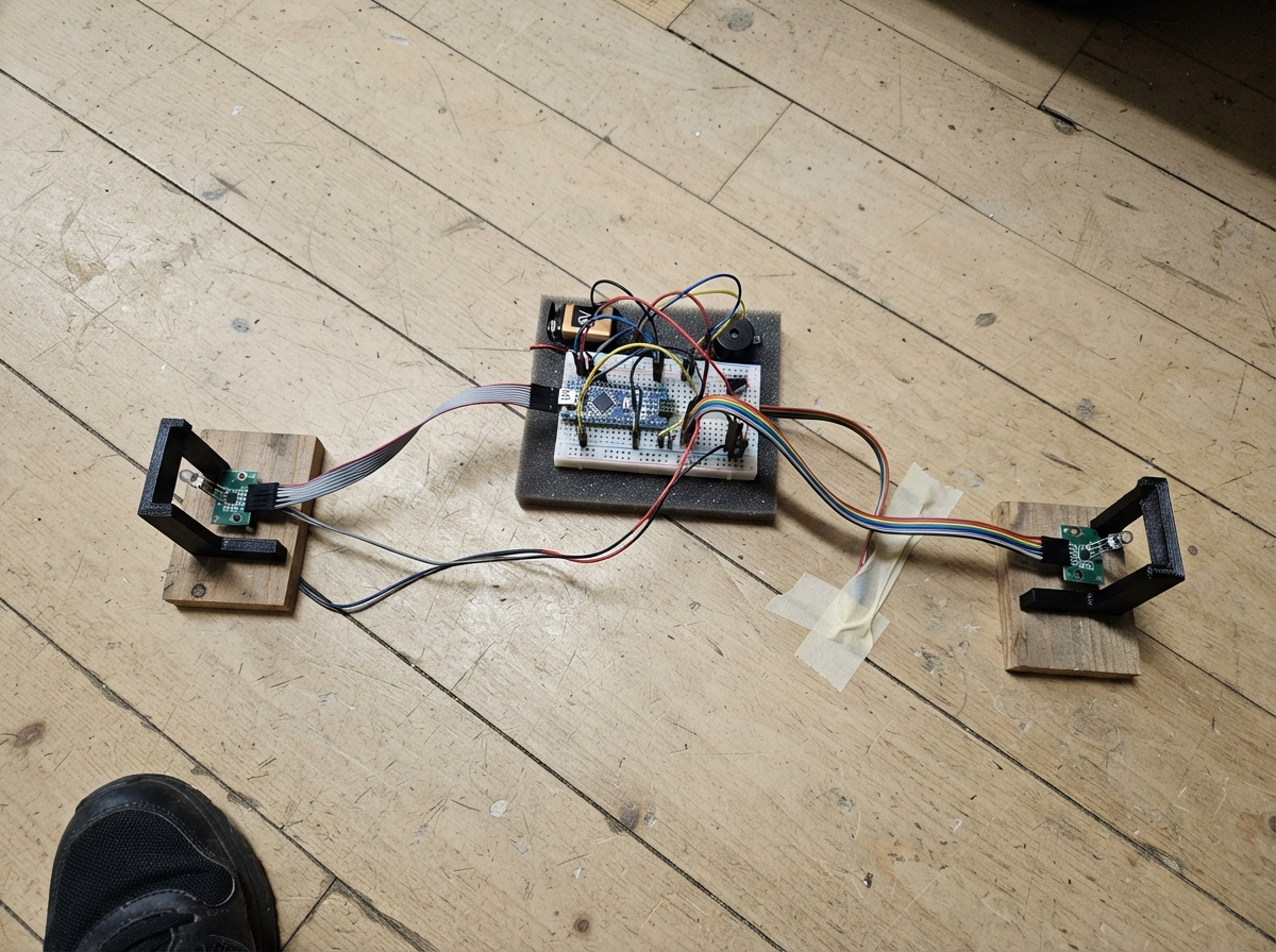
This project builds a speed monitor that detects vehicles passing through two infrared gates and calculates their speed. The ESP32 microcontroller measures the time it takes for a vehicle to travel between the two detectors, then displays the speed on the CardPuter screen and triggers an alarm if the vehicle exceeds the speed limit.
The guide includes a complete wiring diagram showing how to connect both IR detectors to the ESP32, a full parts list, ready-to-upload firmware with interrupt-driven sensor reading and visual/audio alerts, and step-by-step assembly instructions. Builders will learn how to set up dual-gate speed detection, configure debouncing for reliable measurements, and use the CardPuter's display and sound capabilities to monitor traffic in real time.
Wiring diagram

Gather all the parts
Assemble it in 5 steps
1. Place the two infrared detectors
Mount ir_sensor_a where the vehicle enters the sensing area and ir_sensor_b exactly 10 cm farther along the model road. Measure from the center of one infrared window to the center of the other, and aim both at the same part of each passing vehicle.
- Use a stiff strip of wood, plastic, or a baseboard so vibration cannot change the 10 cm gap.
- Turn each sensor’s small adjustment screw until its own indicator changes cleanly as a model car passes.
- If the center-to-center distance is not 10 cm, every speed shown on the screen will be wrong.
2. Connect power to both detectors
At the CardPuter Grove/GPIO breakout, connect each detector VCC to 3.3 V (power) and each detector GND to GND (ground). Both detectors share the same 3.3 V and ground connections.
- Use a Grove splitter or breakout board to share the power wires.
- Use red wire for 3.3 V and black wire for GND so the connections are easy to check.
- Do not connect a detector output that reaches 5 V directly to the CardPuter; more than 3.3 V can damage its input pins.
3. Connect the two detection signals
Connect ir_sensor_a DO to Grove G1 / GPIO1 (first timing signal). Connect ir_sensor_b DO to Grove G2 / GPIO2 (second timing signal). Each detector signal briefly goes low when it sees a vehicle.
- Keep the two signal wires separate and label them A and B.
- The car must pass sensor A first, then sensor B.
- If the signal wires are swapped, the CardPuter waits for the wrong order and does not record a normal pass.
4. Use the CardPuter lights, screen, and sound
Do not wire a separate screen, buzzer, or lamp. The CardPuter’s built-in color LED glows at a low warm-white level while the road is empty, goes bright warm-white after sensor A sees a vehicle, and flashes red for a speeding result. Its built-in screen shows the result and its speaker makes the warning sound.
- The CardPuter color LED is the small built-in light near the top of the device.
- Press the space bar to arm the system for the next vehicle and clear the last result from the display.
- Do not connect wires to the CardPuter’s internal screen, speaker, or color LED; they are already connected inside the device.
5. Test a vehicle pass
Move a test object through ir_sensor_a first and then ir_sensor_b. After sensor B sees it, the screen shows speed from the 10 cm distance and measured travel time. Green NORMAL means the vehicle was within the limit; red SPEEDING!, a sound, and a flashing red CardPuter light mean it was faster than 35 cm/s.
- Start with a slow hand-held object and confirm each sensor module’s own indicator responds.
- Keep fingers, mounting brackets, and cable ties out of the infrared windows to avoid false triggers.
- A loose sensor mount or a vehicle passing extremely close to one sensor can give inconsistent readings.
Review all connections
1. Connections between "ir_sensor_a" and "ESP32"
2. Connections between "ir_sensor_b" and "ESP32"
Deploy the firmware
#include <Arduino.h>
#include <M5Cardputer.h>
#include <FastLED.h>

enum GateState : uint8_t { ARMED, WAITING_FOR_B };


// Forward declarations
void IRAM_ATTR onSensorA();
void IRAM_ATTR onSensorB();
void drawStaticScreen();
void drawStatus();
void drawMeasurement();
void updateIndicator();
void resetForNextVehicle();

constexpr int SENSOR_A_PIN = 1;  // Grove G1 / white wire
constexpr int SENSOR_B_PIN = 2;  // Grove G2 / yellow wire
constexpr uint8_t BUILTIN_LED_PIN = 21;
constexpr uint8_t LED_COUNT = 1;
constexpr float GATE_DISTANCE_CM = 10.0f;
constexpr float SPEED_LIMIT_CM_S = 35.0f;
constexpr uint32_t DEBOUNCE_US = 15000;
constexpr uint32_t MIN_TRAVEL_US = 3000;
constexpr uint32_t MAX_TRAVEL_US = 5000000;
constexpr uint16_t ALARM_TONE_HZ = 1800;
constexpr uint16_t ALARM_DURATION_MS = 300;
constexpr uint32_t WARNING_FLASH_MS = 3000;
constexpr uint32_t FLASH_INTERVAL_MS = 250;

CRGB statusLed[LED_COUNT];
volatile GateState gateState = ARMED;
volatile uint32_t sensorATimeUs = 0;
volatile uint32_t lastAEdgeUs = 0;
volatile uint32_t lastBEdgeUs = 0;
volatile uint32_t travelTimeUs = 0;
volatile bool speedReady = false;

float lastSpeedCmS = 0.0f;
float lastTimeMs = 0.0f;
uint32_t speedingEvents = 0;
bool hasMeasurement = false;
bool overSpeed = false;
bool statusDirty = true;
bool measurementDirty = true;
bool ledDirty = true;
bool vehicleDetected = false;
bool spaceWasDown = false;
uint32_t warningUntilMs = 0;
bool lastFlashPhase = false;

void IRAM_ATTR onSensorA() {
  const uint32_t now = micros();
  if (now - lastAEdgeUs < DEBOUNCE_US) return;
  lastAEdgeUs = now;
  if (gateState == ARMED) {
    sensorATimeUs = now;
    gateState = WAITING_FOR_B;
  }
}

void IRAM_ATTR onSensorB() {
  const uint32_t now = micros();
  if (now - lastBEdgeUs < DEBOUNCE_US) return;
  lastBEdgeUs = now;
  if (gateState == WAITING_FOR_B) {
    const uint32_t elapsed = now - sensorATimeUs;
    gateState = ARMED;
    if (elapsed >= MIN_TRAVEL_US && elapsed <= MAX_TRAVEL_US) {
      travelTimeUs = elapsed;
      speedReady = true;
    }
  }
}

void drawStaticScreen() {
  auto &display = M5Cardputer.Display;
  display.fillScreen(TFT_BLACK);
  display.setTextSize(2);
  display.setTextColor(TFT_CYAN, TFT_BLACK);
  display.setCursor(7, 5);
  display.print("STREET SPEED");
  display.drawFastHLine(0, 27, display.width(), TFT_DARKGREY);
  display.setTextSize(1);
  display.setTextColor(TFT_LIGHTGREY, TFT_BLACK);
  display.setCursor(7, 112);
  display.print("10 cm gate | Limit 35.0 cm/s");
  display.setCursor(7, 125);
  display.print("SPACE: arm next vehicle");
}

void drawStatus() {
  auto &display = M5Cardputer.Display;
  display.fillRect(7, 34, 230, 17, TFT_BLACK);
  display.setTextSize(1);
  display.setCursor(7, 37);
  GateState state;
  noInterrupts();
  state = gateState;
  interrupts();

  if (state == WAITING_FOR_B) {
    display.setTextColor(TFT_YELLOW, TFT_BLACK);
    display.print("VEHICLE: streetlight at full power");
  } else if (!hasMeasurement) {
    display.setTextColor(TFT_GREEN, TFT_BLACK);
    display.print("READY: streetlight energy-saver mode");
  } else {
    display.setTextColor(overSpeed ? TFT_RED : TFT_GREEN, TFT_BLACK);
    display.print(overSpeed ? "SPEEDING! warning active" : "NORMAL: within speed limit");
  }
}

void drawMeasurement() {
  auto &display = M5Cardputer.Display;
  display.fillRect(7, 53, 232, 56, TFT_BLACK);
  display.setTextSize(1);
  display.setTextColor(TFT_LIGHTGREY, TFT_BLACK);
  display.setCursor(7, 55);
  display.print("LAST SPEED");
  display.setTextSize(3);
  display.setTextColor(hasMeasurement ? (overSpeed ? TFT_RED : TFT_GREEN) : TFT_DARKGREY, TFT_BLACK);
  display.setCursor(7, 67);
  if (hasMeasurement) display.printf("%.1f", lastSpeedCmS);
  else display.print("--.-");
  display.setTextSize(1);
  display.print(" cm/s");
  if (hasMeasurement) {
    display.setCursor(145, 79);
    display.setTextColor(TFT_LIGHTGREY, TFT_BLACK);
    display.printf("%.1f ms", lastTimeMs);
  }
  display.fillRect(155, 55, 83, 17, TFT_BLACK);
  display.setCursor(155, 57);
  display.setTextColor(TFT_YELLOW, TFT_BLACK);
  display.printf("Events: %lu", static_cast<unsigned long>(speedingEvents));
}

void updateIndicator() {
  GateState state;
  noInterrupts();
  state = gateState;
  interrupts();
  const uint32_t now = millis();
  const bool warningActive = overSpeed && now < warningUntilMs;
  const bool flashPhase = ((now / FLASH_INTERVAL_MS) % 2U) == 0U;

  if (warningActive && flashPhase != lastFlashPhase) ledDirty = true;
  lastFlashPhase = flashPhase;
  if (!ledDirty) return;

  if (warningActive) {
    statusLed[0] = flashPhase ? CRGB::Red : CRGB::Black;
  } else if (state == WAITING_FOR_B) {
    statusLed[0] = CRGB(255, 220, 170);  // Full-bright warm-white streetlight.
  } else {
    statusLed[0] = CRGB(50, 43, 33);     // Approximately 20% warm-white idle light.
  }
  FastLED.show();
  ledDirty = false;
}

void resetForNextVehicle() {
  noInterrupts();
  gateState = ARMED;
  speedReady = false;
  interrupts();
  hasMeasurement = false;
  overSpeed = false;
  warningUntilMs = 0;
  statusDirty = true;
  measurementDirty = true;
  ledDirty = true;
}

void setup() {
  auto cfg = M5.config();
  M5Cardputer.begin(cfg, true);
  M5Cardputer.Display.setRotation(1);
  FastLED.addLeds<WS2812, BUILTIN_LED_PIN, GRB>(statusLed, LED_COUNT);
  FastLED.setBrightness(255);

  pinMode(SENSOR_A_PIN, INPUT_PULLUP);
  pinMode(SENSOR_B_PIN, INPUT_PULLUP);
  attachInterrupt(digitalPinToInterrupt(SENSOR_A_PIN), onSensorA, FALLING);
  attachInterrupt(digitalPinToInterrupt(SENSOR_B_PIN), onSensorB, FALLING);

  drawStaticScreen();
  drawStatus();
  drawMeasurement();
  statusDirty = false;
  measurementDirty = false;
  updateIndicator();
}

void loop() {
  M5Cardputer.update();
  bool measured = false;
  bool timedOut = false;
  uint32_t elapsedUs = 0;

  noInterrupts();
  if (speedReady) {
    elapsedUs = travelTimeUs;
    speedReady = false;
    measured = true;
  }
  if (gateState == WAITING_FOR_B && micros() - sensorATimeUs > MAX_TRAVEL_US) {
    gateState = ARMED;
    timedOut = true;
  }
  interrupts();

  if (measured) {
    lastTimeMs = static_cast<float>(elapsedUs) / 1000.0f;
    lastSpeedCmS = GATE_DISTANCE_CM * 1000000.0f / static_cast<float>(elapsedUs);
    overSpeed = lastSpeedCmS > SPEED_LIMIT_CM_S;
    hasMeasurement = true;
    if (overSpeed) {
      speedingEvents++;
      warningUntilMs = millis() + WARNING_FLASH_MS;
      M5Cardputer.Speaker.tone(ALARM_TONE_HZ, ALARM_DURATION_MS);
    }
    statusDirty = true;
    measurementDirty = true;
    ledDirty = true;
  }

  if (timedOut) {
    statusDirty = true;
    ledDirty = true;
  }

  const bool spaceDown = M5Cardputer.Keyboard.isKeyPressed(' ');
  if (spaceDown && !spaceWasDown) resetForNextVehicle();
  spaceWasDown = spaceDown;

  if (overSpeed && millis() >= warningUntilMs && warningUntilMs != 0) {
    warningUntilMs = 0;
    ledDirty = true;
  }
  if (statusDirty) {
    drawStatus();
    statusDirty = false;
  }
  if (measurementDirty) {
    drawMeasurement();
    measurementDirty = false;
  }
  updateIndicator();
  delay(3);
}
Remix this project
Make it yours in one click
Open a full copy of this project in your own Schematik workspace — diagram, code, parts, and assembly steps included. Swap the sensor, add features, or redesign the whole thing with AI. The author's original stays untouched.