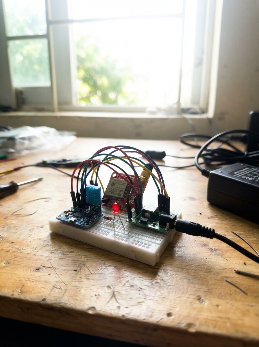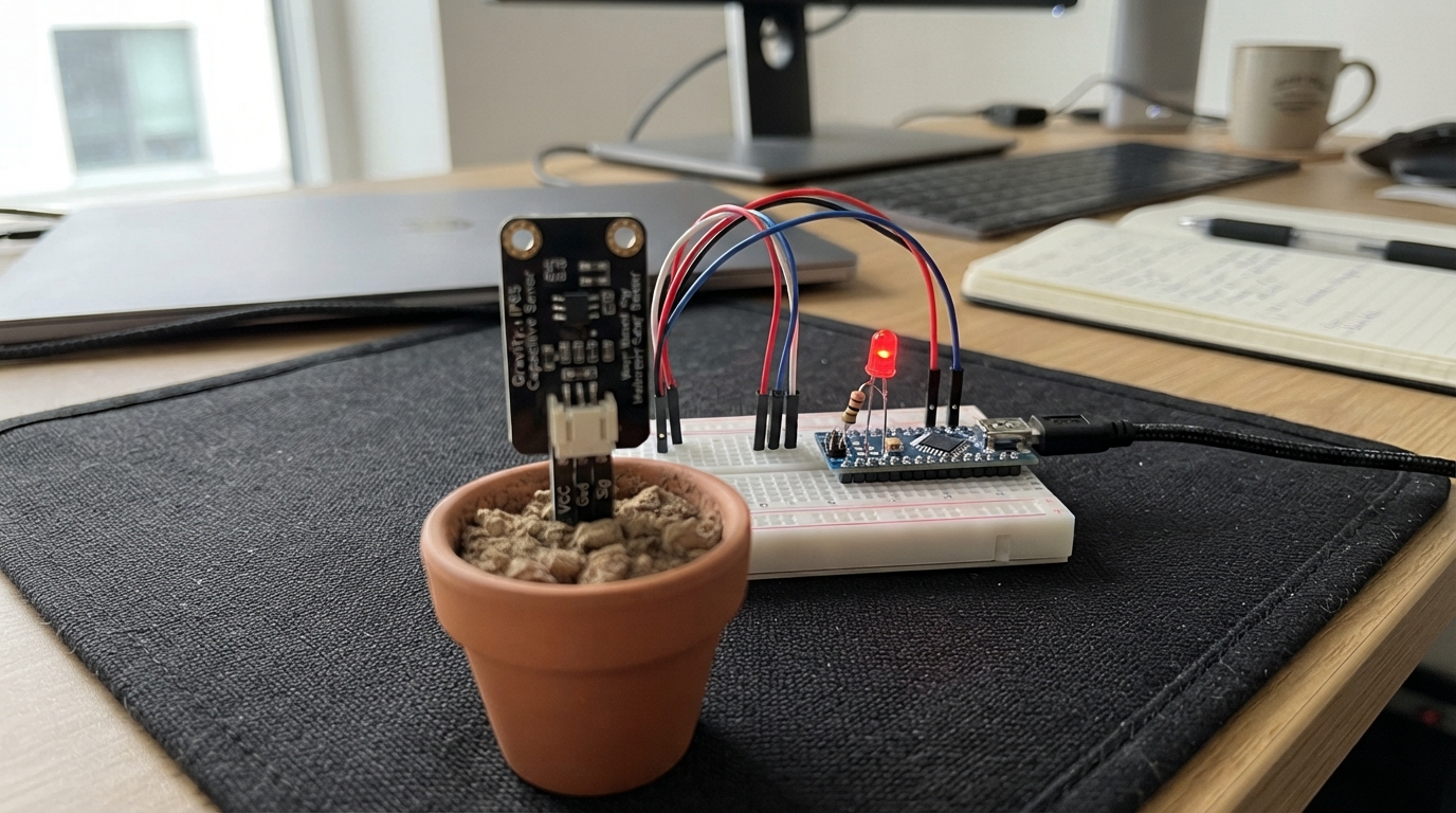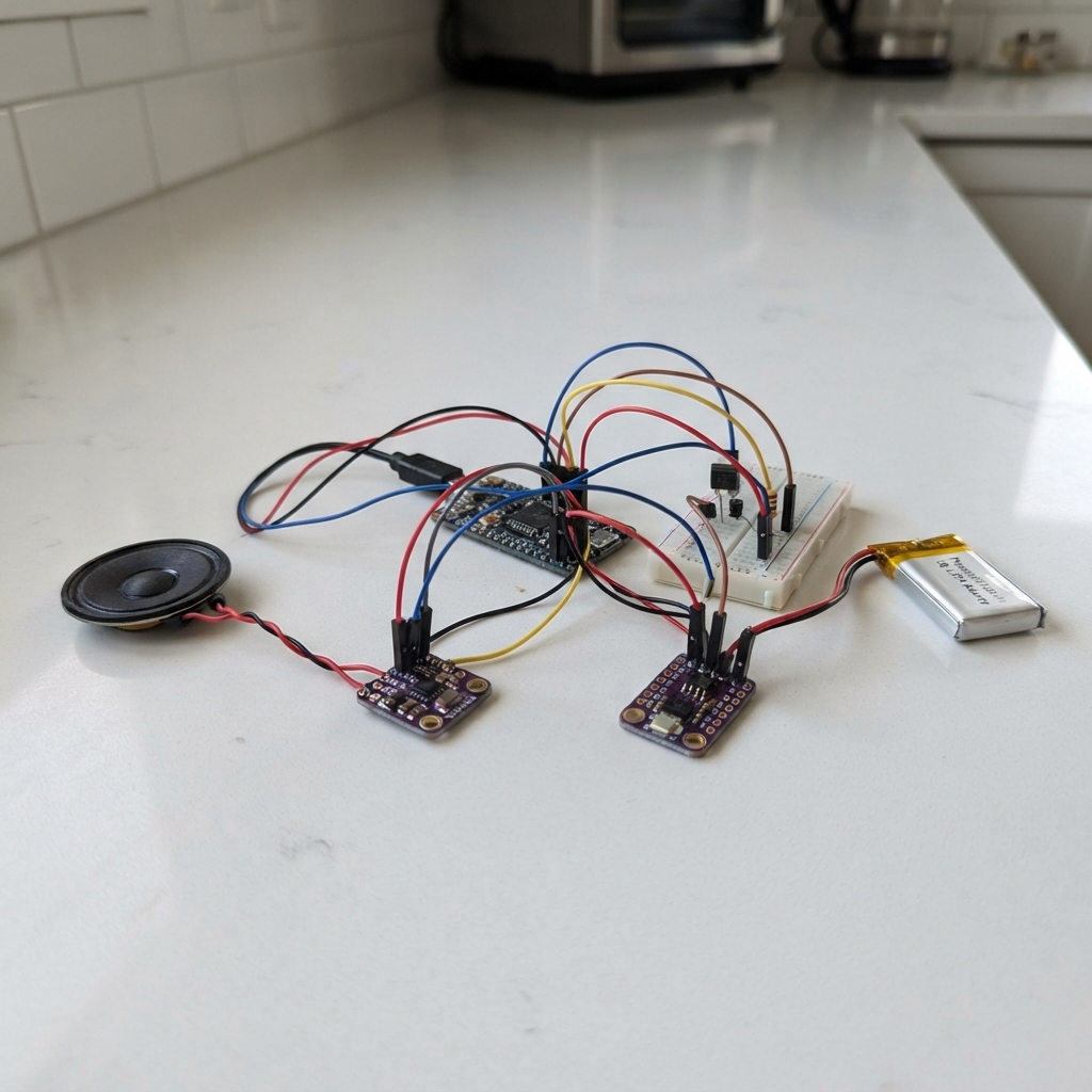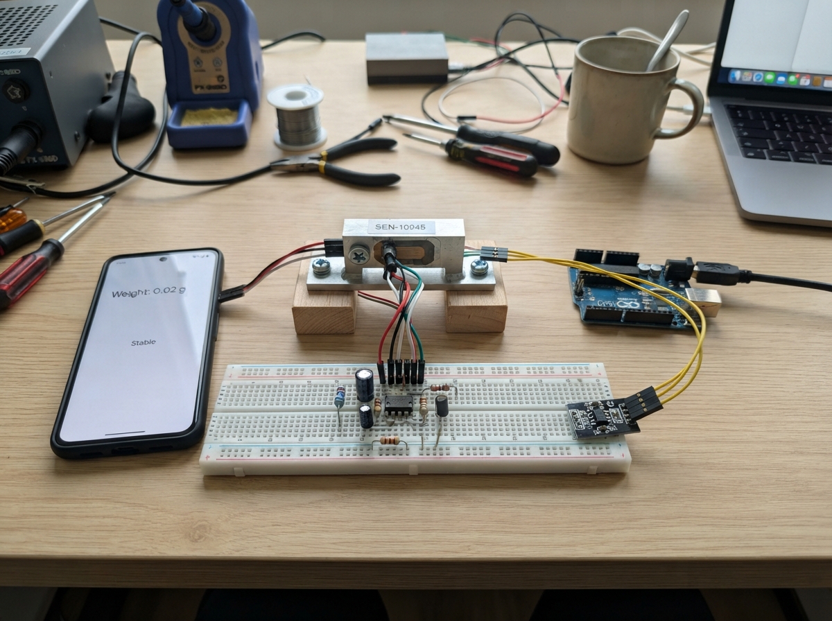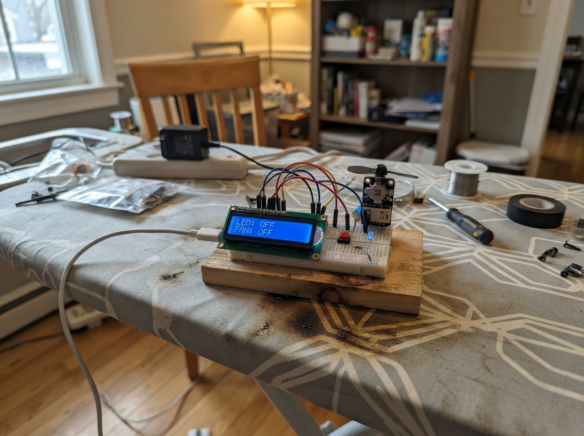
This project builds a simple fan control system using an Arduino Uno, where a push button toggles a small N20 motor on and off. The RGB LED provides visual feedback—red when the fan is off, green when running—while a 16x2 LCD display shows the current fan state. The guide includes a complete wiring diagram, parts list, and step-by-step assembly instructions.
The firmware implements debounced button reading to ensure reliable switching, along with serial communication for remote control via USB. Builders will learn how to wire digital outputs, use I2C communication with the LCD, and write clean Arduino code that handles both physical and serial inputs. This project is ideal for beginners learning to combine multiple components into a functional embedded system.
Wiring diagram
Gather all the parts
Assemble it in 4 steps
1. Remove the distance sensor
Unplug USB and the fan supply. Remove the HC-SR04 and all four of its wires. D5 will control the fan; move the blue LED resistor wire from D5 to D4.
2. Connect the fan module
Use the M5Stack Unit Fan U063, which contains its motor driver and protection. Connect its yellow DIN wire to D5, red VCC wire to the separate regulated 5 V supply positive terminal, and black GND wire to supply negative. Leave the white wire unconnected. Connect supply negative to Uno GND. Fit r4 (10 kΩ) between DIN and GND so the fan stays off during reset.
- Do not connect fan power to a GPIO or the Uno 5V pin. Never join the separate supply positive to Uno 5V.
- Use an enclosed regulated 5 V 2 A supply with labelled low-voltage output terminals. Never open or wire mains equipment.
- Secure the motor and use a guard over its propeller. Keep fingers, hair and loose wires away. Disconnect fan power before handling it.
3. Keep the button and RGB LED
Keep the button between D2 and GND. Keep the common-cathode RGB LED common leg at GND, with D7 through r1 (330 Ω) to red, D6 through r2 (330 Ω) to green, and D4 through r3 (330 Ω) to blue. Red means commanded OFF; green means commanded ON. Blue stays off. Each press toggles the fan, with switch bounce filtered in software.
- Keep a separate series resistor for each LED colour. Check the LED supplier pin diagram.
4. Keep the LCD and test
Keep LCD VCC at Uno 5V, GND at GND, SDA at A4 and SCL at A5. The backpack address is 0x27. Plug in USB and press Deploy, then power the fan supply. The fan starts OFF after reset. Press the button to toggle it. The existing browser GUI also controls it. The LCD shows commanded state, not proof of actual rotation. Press OFF and disconnect fan power when finished; disconnecting the browser alone does not stop it.
Review all connections
1. Connections between "r1" and "Arduino"
2. Connections between "r2" and "Arduino"
3. Connections between "r3" and "Arduino"
4. Connections between "led1" and "Arduino"
5. Connections between "button1" and "Arduino"
6. Connections between "lcd1" and "Arduino"
7. Connections between "fan1" and "Arduino"
8. Connections between "supply1" and "Arduino"
9. Connections between "r4" and "Arduino"
Deploy the firmware
#include <Arduino.h>
#include <Wire.h>
#include <LiquidCrystal_I2C.h>
LiquidCrystal_I2C lcd(0x27,16,2);
constexpr byte RED=7, GREEN=6, BLUE=4, FAN=5, BUTTON=2;
bool enabled=false, lastReading=HIGH, stableReading=HIGH;
unsigned long changed=0;
void updateOutputs() {
  digitalWrite(FAN,enabled?HIGH:LOW);
  digitalWrite(RED,!enabled); digitalWrite(GREEN,enabled); digitalWrite(BLUE,LOW);
  lcd.setCursor(0,1); lcd.print(enabled?F("Fan: ON         "):F("Fan: OFF        "));
}
void report() {Serial.println(enabled?F("ON"):F("OFF"));}
void setFan(bool on) {if(on!=enabled) {enabled=on; updateOutputs();} report();}
void setup() {
  digitalWrite(FAN,LOW); pinMode(FAN,OUTPUT);
  pinMode(RED,OUTPUT); pinMode(GREEN,OUTPUT); pinMode(BLUE,OUTPUT);
  pinMode(BUTTON,INPUT_PULLUP); Serial.begin(9600);
  lcd.init(); lcd.backlight(); lcd.setCursor(0,0); lcd.print(F("Button fan      ")); updateOutputs();
}
void loop() {
  bool reading=digitalRead(BUTTON);
  if(reading!=lastReading) {changed=millis(); lastReading=reading;}
  if(millis()-changed>=30 && reading!=stableReading) {
    stableReading=reading; if(reading==LOW) setFan(!enabled);
  }
  while(Serial.available()) {
    char c=Serial.read();
    if(c=='1'||c=='0') setFan(c=='1');
    else if(c=='?') report();
  }
}
Remix this project
Make it yours in one click
Open a full copy of this project in your own Schematik workspace, diagram, code, parts, and assembly steps included. Swap the sensor, add features, or redesign the whole thing with AI. The author's original stays untouched.