Community project
E-Ink Precision Alarm Clock
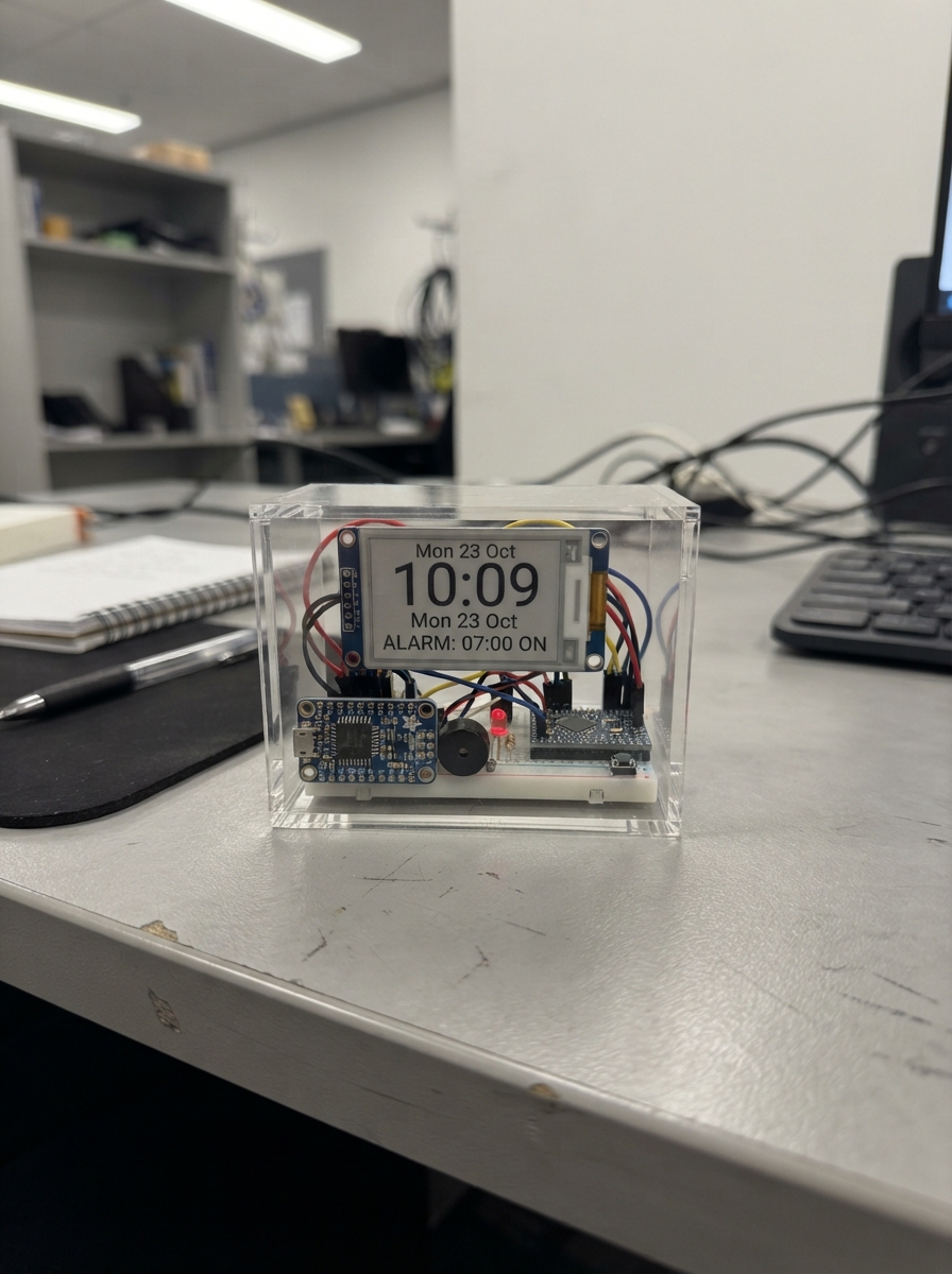
Build a stylish e-ink alarm clock powered by an ESP32 that displays time on a paper-like screen with minimal power draw. The DS3231 precision real-time clock module keeps accurate time even during power loss, while a buzzer provides reliable wake-up alerts and an LED serves as a gentle night light. This guide includes a complete wiring diagram, parts list, and Arduino firmware with button controls for setting the time and alarm.
Assembly takes about an hour and requires only basic soldering skills. The step-by-step instructions cover installing the backup battery, connecting the e-ink display and RTC module via I2C, wiring the buzzer and LED, and programming the three control buttons for easy operation. Once complete, the clock will run for weeks on a single charge thanks to the e-ink display's ultra-low power consumption.
Wiring diagram

Gather all the parts
Assemble it in 7 steps
1. Fit the clock backup battery
With the ESP32 unplugged, slide the CR1220 coin cell into the holder on rtc_ds3231 with its + side facing the marked + side of the holder. This small battery keeps the clock time when USB power is removed.
- Do this before closing the clock case, because the battery holder is easier to reach now.
- Do not force the coin cell backwards — a reversed battery will not keep the clock running.
2. Connect the paper-like screen
Connect epaper_583 VCC to ESP32 3V3 (power), GND to ESP32 GND (ground), DIN to GPIO23 (data), CLK to GPIO18 (clock), CS to GPIO4 (screen select), DC to GPIO27 (screen command/data), RST to GPIO26 (screen reset), and BUSY to GPIO33 (screen-ready signal). Keep these wires short and make sure VCC and GND are not swapped — swapped power can damage the screen.
- The screen keeps its picture even when it is not being refreshed, so a brief pause during a minute change is normal.
- Use only the ESP32 3V3 pin for this screen; connecting the screen power wire to 5V can damage it.
3. Connect the local clock module
Connect rtc_ds3231 VIN to ESP32 3V3 (power), GND to ESP32 GND (ground), SDA to GPIO21 (time data), and SCL to GPIO22 (time clock). The module keeps the time itself, so the ESP32 does not need to keep asking the internet for clock updates.
- All modules must share the same GND connection or their signals cannot be read reliably.
- Do not connect the DS3231 VIN pin to 5V in this build; it is being used as a 3.3V module.
4. Wire the alarm sounder
Connect buzzer_1 SIGNAL to GPIO14 (alarm sound signal) and GND to ESP32 GND (ground). Place its sound hole where it will not be blocked by the case.
- If the buzzer has + and - markings instead of SIGNAL and GND, connect + to GPIO14 and - to GND.
- Do not plug the buzzer directly across 3V3 and GND, because it would sound continuously.
5. Add the gentle night light
Connect night_led_resistor_1 P1 to GPIO25 (light-control signal). Connect its P2 lead to the long positive leg of each warm-white LED in night_led_1 (current limiting). Connect each short LED leg to ESP32 GND (ground). Put the two LEDs behind a frosted window or point them at a white case wall so the light is soft rather than glaring.
- The long LED leg is the positive side. The 1 kΩ resistor deliberately makes the LEDs dim for nighttime viewing.
- Never omit the resistor — direct connection can damage the LEDs or overload the ESP32 pin.
6. Wire the three control buttons
For each button, connect one side to ESP32 GND (ground). Connect button_set SIGNAL to GPIO32 (setting control), button_up SIGNAL to GPIO16 (raise value or toggle light), and button_down SIGNAL to GPIO17 (lower value or toggle light). Use the two opposite legs of each four-leg pushbutton; legs on the same side are already joined inside the button.
- A quick press of SET moves between alarm hour, alarm minute, alarm on/off, and normal display. In normal display, UP or DOWN turns the gentle night light on or off.
- If a button appears stuck, move one wire to the opposite side of the pushbutton; using two legs on the same side does not make a switch connection.
7. Power and test the finished clock
Check every GND wire once more, mount the screen so its front is protected, then connect the ESP32 to a USB power source (power). The clock is designed for USB power, while rtc_ds3231 keeps the local time during short power interruptions.
- Leave access to the three buttons and the ESP32 USB socket after mounting everything in the case.
- Disconnect USB power before moving wires or closing the case, because loose wires can short adjacent pins.
Review all connections
1. Connections between "epaper_583" and "ESP32"
2. Connections between "rtc_ds3231" and "ESP32"
3. Connections between "buzzer_1" and "ESP32"
4. Connections between "night_led_resistor_1" and "ESP32"
5. Connections between "night_led_1" and "ESP32"
6. Connections between "button_set" and "ESP32"
7. Connections between "button_up" and "ESP32"
8. Connections between "button_down" and "ESP32"
Deploy the firmware
#include <Arduino.h>
#include <Wire.h>
#include <SPI.h>
#include <RTClib.h>
#include <GxEPD2_BW.h>
#include <Fonts/FreeMonoBold18pt7b.h>
#include <Fonts/FreeMonoBold24pt7b.h>
#include <Fonts/FreeMonoBold48pt7b.h>


// Forward declarations
bool pressed(int pin);
void drawClock(const DateTime &now);

constexpr int EPD_CS = 4;
constexpr int EPD_DC = 27;
constexpr int EPD_RST = 26;
constexpr int EPD_BUSY = 33;
constexpr int EPD_SCK = 18;
constexpr int EPD_MOSI = 23;
constexpr int RTC_SDA = 21;
constexpr int RTC_SCL = 22;
constexpr int BUZZER_PIN = 14;
constexpr int LIGHT_PIN = 25;
constexpr int SET_PIN = 32;
constexpr int UP_PIN = 16;
constexpr int DOWN_PIN = 17;

GxEPD2_BW<GxEPD2_583, GxEPD2_583::HEIGHT> display(GxEPD2_583(EPD_CS, EPD_DC, EPD_RST, EPD_BUSY));
RTC_DS3231 rtc;

int alarmHour = 7;
int alarmMinute = 0;
bool alarmEnabled = true;
bool alarmRinging = false;
bool nightLight = false;
uint8_t editField = 0; // 0 none, 1 hour, 2 minute, 3 alarm enable
int lastShownMinute = -1;
uint32_t lastButtonMs = 0;

bool pressed(int pin)
{
  if (digitalRead(pin) != LOW || millis() - lastButtonMs < 180) return false;
  lastButtonMs = millis();
  return true;
}

void drawClock(const DateTime &now)
{
  char timeText[6];
  char dateText[28];
  char alarmText[24];
  snprintf(timeText, sizeof(timeText), "%02d:%02d", now.hour(), now.minute());
  snprintf(dateText, sizeof(dateText), "%s %02d %s %04d", "", now.day(), "", now.year());
  const char *days[] = {"Sun", "Mon", "Tue", "Wed", "Thu", "Fri", "Sat"};
  const char *months[] = {"Jan", "Feb", "Mar", "Apr", "May", "Jun", "Jul", "Aug", "Sep", "Oct", "Nov", "Dec"};
  snprintf(dateText, sizeof(dateText), "%s, %s %d, %d", days[now.dayOfTheWeek()], months[now.month() - 1], now.day(), now.year());
  snprintf(alarmText, sizeof(alarmText), "ALARM  %s  %02d:%02d", alarmEnabled ? "ON" : "OFF", alarmHour, alarmMinute);

  display.setFullWindow();
  display.firstPage();
  do
  {
    display.fillScreen(GxEPD2_WHITE);
    display.setTextColor(GxEPD2_BLACK);
    display.setFont(&FreeMonoBold18pt7b);
    display.setCursor(38, 48);
    display.print(dateText);
    display.drawLine(38, 68, 562, 68, GxEPD2_BLACK);
    display.setFont(&FreeMonoBold48pt7b);
    display.setCursor(53, 250);
    display.print(timeText);
    display.drawLine(38, 292, 562, 292, GxEPD2_BLACK);
    display.setFont(&FreeMonoBold24pt7b);
    display.setCursor(55, 350);
    display.print(alarmText);
    display.setFont(&FreeMonoBold18pt7b);
    display.setCursor(38, 414);
    if (editField == 0) display.print("SET: edit   UP/DOWN: change   hold SET: night light");
    else if (editField == 1) display.print("Editing alarm hour");
    else if (editField == 2) display.print("Editing alarm minute");
    else display.print("Editing alarm on/off");
  }
  while (display.nextPage());
}

void setup()
{
  pinMode(BUZZER_PIN, OUTPUT);
  pinMode(LIGHT_PIN, OUTPUT);
  pinMode(SET_PIN, INPUT_PULLUP);
  pinMode(UP_PIN, INPUT_PULLUP);
  pinMode(DOWN_PIN, INPUT_PULLUP);
  analogWrite(LIGHT_PIN, 0);
  Wire.begin(RTC_SDA, RTC_SCL);
  rtc.begin();
  if (rtc.lostPower()) rtc.adjust(DateTime(F(__DATE__), F(__TIME__)));
  SPI.begin(EPD_SCK, -1, EPD_MOSI, EPD_CS);
  display.init(115200, true, 2, false);
  drawClock(rtc.now());
}

void loop()
{
  DateTime now = rtc.now();
  if (pressed(SET_PIN))
  {
    if (alarmRinging)
    {
      alarmRinging = false;
      noTone(BUZZER_PIN);
    }
    else
    {
      editField = (editField + 1) % 4;
      drawClock(now);
    }
  }
  if (pressed(UP_PIN))
  {
    if (editField == 1) alarmHour = (alarmHour + 1) % 24;
    else if (editField == 2) alarmMinute = (alarmMinute + 1) % 60;
    else if (editField == 3) alarmEnabled = !alarmEnabled;
    else nightLight = !nightLight;
    analogWrite(LIGHT_PIN, nightLight ? 18 : 0);
    drawClock(now);
  }
  if (pressed(DOWN_PIN))
  {
    if (editField == 1) alarmHour = (alarmHour + 23) % 24;
    else if (editField == 2) alarmMinute = (alarmMinute + 59) % 60;
    else if (editField == 3) alarmEnabled = !alarmEnabled;
    else nightLight = !nightLight;
    analogWrite(LIGHT_PIN, nightLight ? 18 : 0);
    drawClock(now);
  }
  if (alarmEnabled && now.hour() == alarmHour && now.minute() == alarmMinute && now.second() < 2)
  {
    alarmRinging = true;
  }
  if (alarmRinging)
  {
    tone(BUZZER_PIN, 2200);
  }
  else
  {
    noTone(BUZZER_PIN);
  }
  if (now.minute() != lastShownMinute)
  {
    lastShownMinute = now.minute();
    drawClock(now);
  }
  delay(40);
}
Remix this project
Make it yours in one click
Open a full copy of this project in your own Schematik workspace — diagram, code, parts, and assembly steps included. Swap the sensor, add features, or redesign the whole thing with AI. The author's original stays untouched.