Community project
Esp 32 Dev Kit One Display Dac Amp
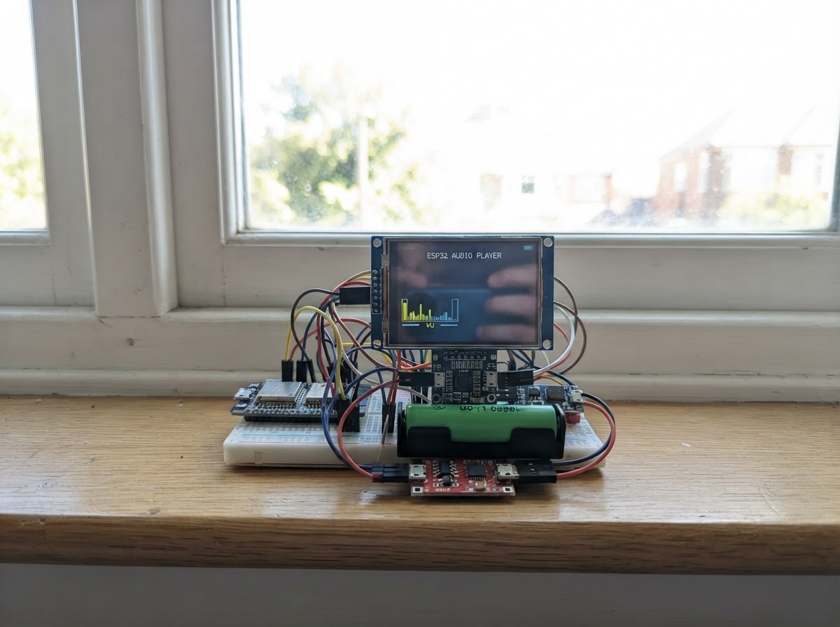
This project builds a portable Bluetooth audio player and task manager with a vibrant 3.5-inch touchscreen display. The ESP32 Dev Kit One connects to an I2S DAC for high-quality audio output, a TP4056 charger for safe 18650 battery management, and a step-up/step-down regulator to maintain stable 5V power across all components.
The guide provides a complete wiring diagram showing all connections between the display, touch controller, audio board, battery charging circuit, and power regulation. Builders will receive a full parts list, step-by-step assembly instructions, and Arduino firmware that enables Bluetooth A2DP streaming, touchscreen task tracking, and real-time display updates—everything needed to assemble and deploy a functional audio device.
Wiring diagram

Gather all the parts
Assemble it in 8 steps
1. Place the boards with power unplugged
Put the Denky32, 3.5-inch screen, headphone DAC, 18650 holder, TP4056 charger, and 5 V converter on a non-metal surface. Keep all USB power unplugged and leave the 18650 cell out of its holder while adding wires.
- Use an insulated 18650 holder; never solder directly onto the battery cell.
- Do not let the battery positive and negative wires touch — a short circuit can make the cell or wires dangerously hot.
2. Connect the display power and backlight
Connect Denky32 3V3 to the screen VCC (power), Denky32 GND to screen GND (ground), and Denky32 3V3 to screen LED (backlight power).
- Some screens label their 3.3 V power pin VCC or 3V3.
- Do not connect the screen VCC or LED pin to 5V/VIN — 5 V can damage a 3.3 V screen.
3. Connect the screen picture and touch wires
Connect screen SCK to GPIO18 (picture timing), MOSI or SDI to GPIO23 (picture data), MISO or SDO to GPIO19 (touch return data), CS to GPIO4 (screen select), DC to GPIO32 (screen control), RESET to GPIO33 (screen restart), and T_CS/TCS/TP_CS to GPIO27 (touch select). Leave T_IRQ unconnected.
- Keep SCK, MOSI, and MISO short so the screen picture stays stable.
- This wiring is only for an SPI ILI9488 display; do not use it with an Arduino UNO-style parallel display shield.
4. Connect the headphone audio board
Connect the headphone DAC VCC to Denky32 3V3 (power), GND to Denky32 GND (ground), BCK/BCLK to GPIO26 (audio timing), LCK/WSEL to GPIO14 (left/right timing), and DIN to GPIO13 (sound data).
- Plug earphones into the DAC board's 3.5 mm socket only after the power wiring is complete.
- Do not connect earphones to a speaker-amplifier output; start your phone volume low to protect your hearing.
5. Wire the battery to the charger
Put the protected 18650 in its holder with the raised end at the holder’s + mark. Connect holder positive to TP4056 B+ (battery power) and holder negative to TP4056 B- (battery ground).
- Use a six-pad TP4056 board with B+/B- and OUT+/OUT- pads, plus a USB-C charging socket.
- Do not reverse B+ and B- — reversed battery wiring can destroy the charger board and overheat the cell.
6. Connect the protected output and 5 V converter
Connect TP4056 OUT+ to the converter VIN (battery power), TP4056 OUT- to converter GND (ground), and converter VOUT to the Denky32 5V/VIN pin (board power). The converter ground is already connected back through TP4056 OUT-.
- Before connecting VOUT to the Denky32, use a meter to set and confirm the converter output is 5.0 V.
- Never connect the raw 3.7 V battery or TP4056 OUT+ directly to the Denky32 5V/VIN pin. A converter set above 5.0 V can damage the board.
7. Charge the cell through the charger board
Connect a normal 5 V USB supply to the TP4056 USB-C charging input. This charges the 18650; remove that charging cable before using the project if your TP4056 module cannot power a load while charging.
- The TP4056 charge light normally changes color or turns off when charging is complete.
- Do not try to charge the 18650 from the Denky32 USB connector — that connector has no lithium-battery charger.
8. Power, deploy, and use it
With the 5 V converter connected to Denky32 5V/VIN, connect the Denky32 USB port to your computer only when you want to deploy firmware. Press Deploy in Schematik, then pair your phone with TaskList IEM DAC and tap task squares on the screen.
- One 2200 mAh cell is expected to run for roughly 4–6 hours; carry a second charged cell only if you have a holder designed for safe cell changes.
- Do not connect the battery-powered 5V/VIN input and a computer USB cable at the same time unless your board’s power path is known to prevent back-feeding.
Review all connections
1. Connections between "tft_35" and "ESP32"
2. Connections between "audio_dac" and "ESP32"
3. Connections between "cell_18650_2200" and "ESP32"
4. Connections between "charger_tp4056" and "ESP32"
5. Connections between "boost_5v" and "ESP32"
Deploy the firmware
#include <Arduino.h>
#include <SPI.h>
#include <Arduino_GFX_Library.h>
#include <XPT2046_Touchscreen.h>
#include <BluetoothA2DPSink.h>

void drawTask(uint8_t index);
void drawScreen();
void connectionStateChanged(esp_a2d_connection_state_t state, void *);

constexpr int TFT_SCK = 18;
constexpr int TFT_MOSI = 23;
constexpr int TFT_MISO = 19;
constexpr int TFT_CS = 4;
constexpr int TFT_DC = 32;
constexpr int TFT_RST = 33;
constexpr int TOUCH_CS = 27;
constexpr int I2S_BCK = 26;
constexpr int I2S_LRCK = 14;
constexpr int I2S_DOUT = 13;

Arduino_DataBus *displayBus = new Arduino_ESP32SPI(TFT_DC, TFT_CS, TFT_SCK, TFT_MOSI, TFT_MISO);
Arduino_GFX *gfx = new Arduino_ILI9488_18bit(displayBus, TFT_RST, 1, false);
XPT2046_Touchscreen touch(TOUCH_CS);
BluetoothA2DPSink bluetooth;

const char *tasks[] = {"Plan today", "Answer messages", "Take a break", "Finish one task", "Review tomorrow"};
constexpr uint8_t TASK_COUNT = sizeof(tasks) / sizeof(tasks[0]);
bool complete[TASK_COUNT] = {false, false, false, false, false};
bool redrawNeeded = true;
bool connected = false;
uint32_t lastTouchMs = 0;

void drawTask(uint8_t index) {
  const int y = 78 + index * 44;
  gfx->fillRect(12, y, 456, 38, 0xFFFF);
  gfx->drawRect(17, y + 7, 24, 24, 0x7BEF);
  if (complete[index]) {
    gfx->fillRect(20, y + 10, 18, 18, 0x07E0);
    gfx->setTextColor(0x07E0, 0xFFFF);
    gfx->setCursor(21, y + 26);
    gfx->print("+");
  }
  gfx->setTextColor(complete[index] ? 0x7BEF : 0x2104, 0xFFFF);
  gfx->setTextSize(2);
  gfx->setCursor(55, y + 11);
  gfx->print(tasks[index]);
  gfx->drawFastHLine(12, y + 39, 456, 0xC618);
}

void drawScreen() {
  gfx->fillScreen(0xFFFF);
  gfx->fillRect(0, 0, 480, 58, 0x087D);
  gfx->setTextColor(0xFFFF, 0x087D);
  gfx->setTextSize(3);
  gfx->setCursor(14, 16);
  gfx->print("MY TASK LIST");
  gfx->setTextSize(2);
  gfx->setCursor(305, 20);
  gfx->print(connected ? "BT CONNECTED" : "BT READY");
  gfx->setTextColor(0x4208, 0xFFFF);
  gfx->setTextSize(1);
  gfx->setCursor(15, 65);
  gfx->print("Tap a square to mark the task done");
  for (uint8_t i = 0; i < TASK_COUNT; ++i) drawTask(i);
}

void connectionStateChanged(esp_a2d_connection_state_t state, void *) {
  connected = (state == ESP_A2D_CONNECTION_STATE_CONNECTED);
  redrawNeeded = true;
}

void setup() {
  Serial.begin(115200);
  SPI.begin(TFT_SCK, TFT_MISO, TFT_MOSI);
  gfx->begin();
  gfx->setRotation(1);
  touch.begin(SPI);
  touch.setRotation(1);
  drawScreen();
  i2s_pin_config_t audioPins = {.bck_io_num = I2S_BCK, .ws_io_num = I2S_LRCK, .data_out_num = I2S_DOUT, .data_in_num = I2S_PIN_NO_CHANGE};
  bluetooth.set_pin_config(audioPins);
  bluetooth.set_on_connection_state_changed(connectionStateChanged);
  bluetooth.start("TaskList IEM DAC");
}

void loop() {
  if (redrawNeeded) { redrawNeeded = false; drawScreen(); }
  if (!touch.touched() || millis() - lastTouchMs < 180) return;
  TS_Point point = touch.getPoint();
  lastTouchMs = millis();
  int screenY = map(point.y, 200, 3800, 0, 320);
  if (screenY < 78 || screenY > 298) return;
  uint8_t index = (screenY - 78) / 44;
  if (index < TASK_COUNT) { complete[index] = !complete[index]; drawTask(index); }
}
Remix this project
Make it yours in one click
Open a full copy of this project in your own Schematik workspace — diagram, code, parts, and assembly steps included. Swap the sensor, add features, or redesign the whole thing with AI. The author's original stays untouched.