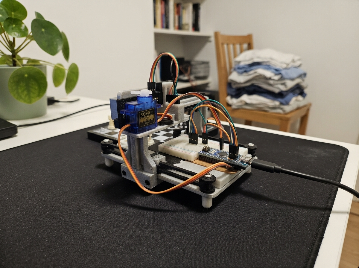
This project builds a chess piece pusher robot using an ESP32 microcontroller and a small SG90 servo motor. The servo acts as a finger to nudge chess pieces across the board with precise, controlled movements. Builders will receive a complete wiring diagram, parts list, step-by-step assembly instructions, and tested firmware that controls the servo via serial commands.
The guide emphasizes safe assembly practices, including a mandatory wiring review before powering any components and separate power management for the servo motor. Once assembled and verified, the robot responds to simple serial commands to center the finger, push left, push right, or release the servo. This project is ideal for makers learning servo control and automation basics.
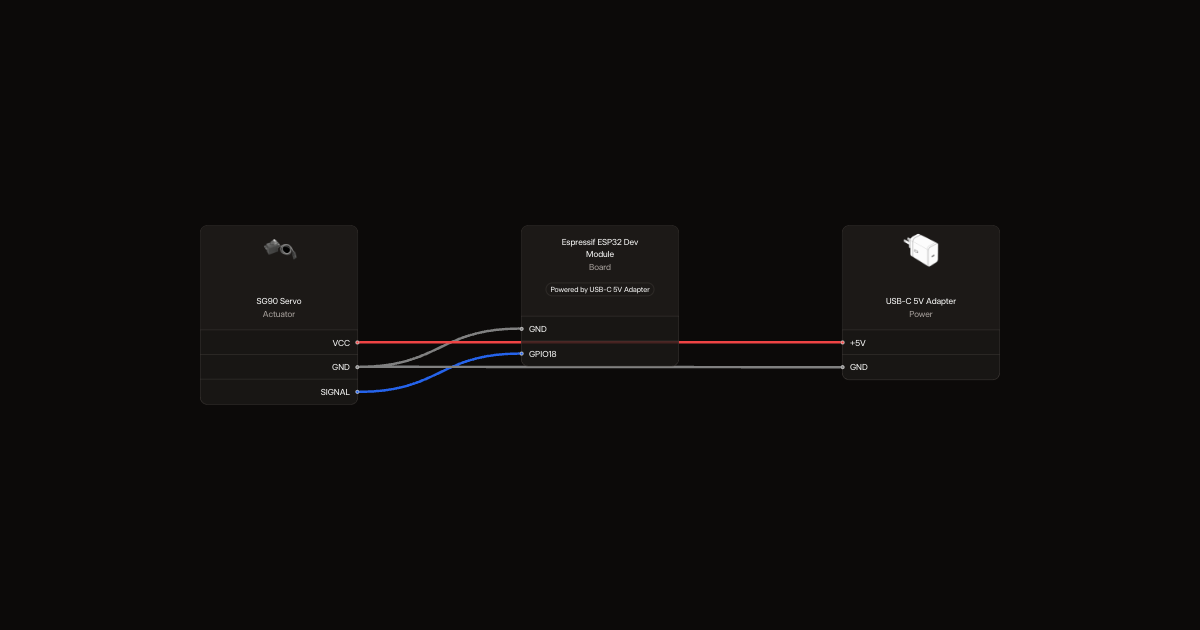
Wiring diagram
Gather all the parts
Assemble it in 5 steps
1. Stop before powering anything
This first phase is an unloaded one-servo test, not an arm. Leave USB and servo supply disconnected. This pin plan is for a classic ESP32-WROOM dev board, not an S3 or C3. Confirm the board matches before wiring.
2. Prepare separate motor power
Use an enclosed regulated 5 V supply rated at least 2 A with a suitable insulated low-voltage USB breakout cable. Do not cut mains wiring. With nothing connected, verify its output voltage and polarity using your multimeter, then unplug it.
- Never connect servo power to the ESP32 3.3 V pin or join the supply positive to the ESP32 USB/5 V rail.
3. Connect the unloaded servo
Remove the horn and any arm. Connect servo SIGNAL to GPIO18 (control), servo VCC to the separate supply +5V (motor power), and servo GND to supply GND and ESP32 GND (shared signal reference). Verify lead markings; do not rely on colour alone. Use secure insulated connections for motor power.
4. Share the unpowered wiring photo
Keep both supplies disconnected. Share a clear photo showing board labels, servo leads, and power connections. Wait for review before any circuit power-on. A photo cannot prove voltage or polarity.
5. Test only after review
Keep the servo unloaded. The firmware starts idle and only moves after a manual serial command. Done when ten small commanded moves complete without heating, buzzing against a stop, or ESP32 resets. Disconnect servo power immediately if anything behaves unexpectedly.
Review all connections
1. Connections between "servo1" and "ESP32"
2. Connections between "supply1" and "ESP32"
Deploy the firmware
#include <Arduino.h>
#include <ESP32Servo.h>
Servo finger;
constexpr int SERVO_PIN = 18;
void setup() {
  Serial.begin(115200);
  pinMode(SERVO_PIN, OUTPUT);
  digitalWrite(SERVO_PIN, LOW);
  Serial.println("Servo idle. After wiring review: c=center, l=small left, r=small right, s=release.");
}
void loop() {
  if (!Serial.available()) return;
  char command = Serial.read();
  if (command == 's') {
    finger.detach();
    pinMode(SERVO_PIN, OUTPUT);
    digitalWrite(SERVO_PIN, LOW);
    Serial.println("Released; disconnect supply to remove power.");
  } else if (command == 'c' || command == 'l' || command == 'r') {
    if (!finger.attached()) {
      finger.setPeriodHertz(50);
      finger.attach(SERVO_PIN, 1000, 2000);
    }
    int pulse = command == 'l' ? 1400 : command == 'r' ? 1600 : 1500;
    finger.writeMicroseconds(pulse);
    Serial.printf("Pulse: %d us\n", pulse);
  }
}
Remix this project
Make it yours in one click
Open a full copy of this project in your own Schematik workspace, diagram, code, parts, and assembly steps included. Swap the sensor, add features, or redesign the whole thing with AI. The author's original stays untouched.