Community project
ESP32 Car Remote Control
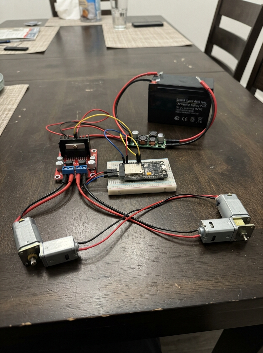
This project turns a 12V car into a WiFi-controlled vehicle using an ESP32 microcontroller. The system uses dual IBT-2 H-bridge motor drivers to independently control left and right drive motors, with a 24V buck converter stepping down the car battery to safe logic levels. Builders get a complete wiring diagram, parts list, and step-by-step assembly instructions that cover motor controller mounting, power distribution, and safe testing procedures.
The ESP32 runs a web-based control interface accessible over WiFi, allowing directional commands to be sent to each motor with PWM speed control. The firmware includes safety features like command timeouts and moderate initial power limits. This guide walks through battery disconnection, component installation, electrical connections, and verification testing with the car safely elevated.
Wiring diagram

Gather all the parts
Assemble it in 6 steps
1. Desconecta la batería y revisa el auto
Apaga el auto, desconecta un cable de su batería de 12 V y levanta las ruedas motrices para que no toquen el suelo. Identifica los dos cables de cada motor: uno corresponde al motor izquierdo y el otro al derecho.
- Haz las primeras pruebas con las ruedas elevadas para que el auto no pueda salir disparado.
- No trabajes con la batería conectada: un cable grueso tocando el lugar equivocado puede calentarse, quemar un conector o dañar la batería.
2. Monta los controladores de motor
Fija motor_driver_left y motor_driver_right sobre una base no metálica, separados de la placa ESP32. Deja espacio para que circule aire alrededor de ellos y usa cable grueso para los cables de batería y motor.
- Etiqueta un controlador como IZQUIERDO y el otro como DERECHO antes de conectar cables.
- No montes los controladores donde puedan tocar metal del chasis: un contacto puede crear un cortocircuito.
3. Conecta batería, motores y convertidor
Conecta battery_12v +12V a B+ de motor_driver_left, B+ de motor_driver_right y VIN+ de buck_5v (alimentación). Conecta battery_12v 0V a B- de ambos controladores y VIN- de buck_5v (retorno común). Conecta M+ y M- de motor_driver_left a los dos cables M+ y M- de left_motor; repite M+ y M- de motor_driver_right hacia right_motor (potencia de los motores). Ajusta buck_5v a exactamente 5.0 V antes de conectar su salida a la placa.
- Mide la salida VOUT+ y VOUT- del convertidor con un multímetro antes de conectar el ESP32.
- Si una rueda gira al revés durante la prueba, desconecta la batería y cambia entre sí los dos cables de ese motor.
- No conectes los 12 V de la batería al pin 5V/VIN del ESP32 ni a VCC del BTS7960: ese voltaje puede destruirlos.
- Usa un fusible adecuado cerca del positivo de la batería; el valor debe corresponder a la corriente real de los motores y al cableado original del auto.
4. Alimenta la placa y las entradas de los controladores
Conecta VOUT+ de buck_5v al pin VIN/5V del ESP32 y también al pin VCC de motor_driver_left y motor_driver_right (alimentación de 5 V). Conecta VOUT- de buck_5v al pin GND del ESP32 y a GND de ambos controladores (tierra común).
- Todos los GND deben quedar unidos; sin este retorno común las órdenes de la placa no se entienden correctamente.
- Revisa con calma que la salida del convertidor sea 5.0 V y que VCC y GND no estén intercambiados — invertirlos puede dañar la placa y los controladores.
5. Conecta los cables finos de control
En motor_driver_left conecta RPWM → GPIO25 (señal), LPWM → GPIO26 (señal), R_EN → GPIO27 (habilita el controlador) y L_EN → GPIO14 (habilita el controlador). En motor_driver_right conecta RPWM → GPIO32 (señal), LPWM → GPIO33 (señal), R_EN → GPIO13 (habilita el controlador) y L_EN → GPIO4 (habilita el controlador).
- Usa cables cortos para estas señales y mantenlos alejados de los cables gruesos de motor para reducir interferencias.
- No cambies los cables de señal con el auto energizado; una orden accidental puede hacer girar las ruedas.
6. Prueba el control con el auto elevado
Vuelve a conectar la batería, enchufa el ESP32 por USB solo para cargar el programa desde Schematik y luego conéctate desde el teléfono a la red Wi‑Fi Auto12V-Control con clave ControlAuto12. Abre en el navegador la dirección 192.168.4.1 y mantén pulsada una flecha. Suelta el botón para detener el auto.
- Primero prueba avance y parada; después verifica izquierda, derecha y retroceso.
- El control corta los motores si el teléfono deja de enviar órdenes durante aproximadamente un tercio de segundo.
- No pruebes con un niño dentro ni con las ruedas en el suelo hasta confirmar que cada flecha y el botón rojo detienen el auto correctamente.
Review all connections
1. Connections between "battery_12v" and "ESP32"
2. Connections between "buck_5v" and "ESP32"
3. Connections between "motor_driver_left" and "ESP32"
4. Connections between "motor_driver_right" and "ESP32"
Deploy the firmware
#include <WiFi.h>
#include <WebServer.h>

const char *AP_SSID = "Auto12V-Control";
const char *AP_PASSWORD = "ControlAuto12"; // Cambie esta clave antes de usarlo en público.

constexpr int LEFT_FORWARD_PIN = 25;
constexpr int LEFT_REVERSE_PIN = 26;
constexpr int LEFT_ENABLE_A_PIN = 27;
constexpr int LEFT_ENABLE_B_PIN = 14;
constexpr int RIGHT_FORWARD_PIN = 32;
constexpr int RIGHT_REVERSE_PIN = 33;
constexpr int RIGHT_ENABLE_A_PIN = 13;
constexpr int RIGHT_ENABLE_B_PIN = 4;

constexpr uint32_t PWM_FREQUENCY = 20000;
constexpr uint8_t PWM_RESOLUTION = 8;
constexpr int DRIVE_POWER = 210; // 0 a 255; limite inicial moderado.
constexpr unsigned long COMMAND_TIMEOUT_MS = 350;

WebServer server(80);
unsigned long lastCommandMs = 0;

const char CONTROL_PAGE[] PROGMEM = R"rawliteral(
<!doctype html><html lang="es"><head><meta name="viewport" content="width=device-width,initial-scale=1,user-scalable=no"><style>
body{margin:0;background:#111;color:#fff;font-family:Arial;text-align:center;touch-action:manipulation}h2{margin:18px}.grid{display:grid;grid-template-columns:repeat(3,92px);gap:12px;justify-content:center}button{height:82px;border:0;border-radius:14px;background:#2962ff;color:#fff;font-size:28px;font-weight:bold;box-shadow:0 4px #102a70}button:active{transform:translateY(3px);box-shadow:0 1px #102a70}.stop{background:#d32f2f;box-shadow:0 4px #701010}.note{font-size:14px;color:#bbb;margin:22px}
</style></head><body><h2>Control del auto</h2><div class="grid"><span></span><button data-c="F">▲</button><span></span><button data-c="L">◀</button><button class="stop" data-c="S">■</button><button data-c="R">▶</button><span></span><button data-c="B">▼</button><span></span></div><p class="note">Mantenga pulsada una flecha para mover. Al soltar, el auto se detiene.</p><script>
let timer=null; function send(c){fetch('/cmd?c='+c,{cache:'no-store'}).catch(()=>{});} document.querySelectorAll('button').forEach(b=>{let c=b.dataset.c;const go=e=>{e.preventDefault();send(c);if(c!='S')timer=setInterval(()=>send(c),100)};const halt=e=>{e.preventDefault();clearInterval(timer);timer=null;send('S')};b.addEventListener('pointerdown',go);b.addEventListener('pointerup',halt);b.addEventListener('pointerleave',halt);b.addEventListener('pointercancel',halt);});
</script></body></html>
)rawliteral";

void setMotor(int forwardPin, int reversePin, int value) {
  value = constrain(value, -255, 255);
  if (value > 0) {
    ledcWrite(forwardPin, value);
    ledcWrite(reversePin, 0);
  } else if (value < 0) {
    ledcWrite(forwardPin, 0);
    ledcWrite(reversePin, -value);
  } else {
    ledcWrite(forwardPin, 0);
    ledcWrite(reversePin, 0);
  }
}

void stopMotors() {
  setMotor(LEFT_FORWARD_PIN, LEFT_REVERSE_PIN, 0);
  setMotor(RIGHT_FORWARD_PIN, RIGHT_REVERSE_PIN, 0);
}

void drive(char command) {
  int left = 0;
  int right = 0;
  if (command == 'F') { left = DRIVE_POWER; right = DRIVE_POWER; }
  if (command == 'B') { left = -DRIVE_POWER; right = -DRIVE_POWER; }
  if (command == 'L') { left = -DRIVE_POWER; right = DRIVE_POWER; }
  if (command == 'R') { left = DRIVE_POWER; right = -DRIVE_POWER; }
  setMotor(LEFT_FORWARD_PIN, LEFT_REVERSE_PIN, left);
  setMotor(RIGHT_FORWARD_PIN, RIGHT_REVERSE_PIN, right);
}

void handleCommand() {
  char command = server.hasArg("c") ? server.arg("c")[0] : 'S';
  if (command == 'F' || command == 'B' || command == 'L' || command == 'R') {
    drive(command);
    lastCommandMs = millis();
  } else {
    stopMotors();
    lastCommandMs = 0;
  }
  server.send(200, "text/plain", "OK");
}

void setup() {
  pinMode(LEFT_ENABLE_A_PIN, OUTPUT);
  pinMode(LEFT_ENABLE_B_PIN, OUTPUT);
  pinMode(RIGHT_ENABLE_A_PIN, OUTPUT);
  pinMode(RIGHT_ENABLE_B_PIN, OUTPUT);
  digitalWrite(LEFT_ENABLE_A_PIN, HIGH);
  digitalWrite(LEFT_ENABLE_B_PIN, HIGH);
  digitalWrite(RIGHT_ENABLE_A_PIN, HIGH);
  digitalWrite(RIGHT_ENABLE_B_PIN, HIGH);

  ledcAttach(LEFT_FORWARD_PIN, PWM_FREQUENCY, PWM_RESOLUTION);
  ledcAttach(LEFT_REVERSE_PIN, PWM_FREQUENCY, PWM_RESOLUTION);
  ledcAttach(RIGHT_FORWARD_PIN, PWM_FREQUENCY, PWM_RESOLUTION);
  ledcAttach(RIGHT_REVERSE_PIN, PWM_FREQUENCY, PWM_RESOLUTION);
  stopMotors();

  WiFi.mode(WIFI_AP);
  WiFi.softAP(AP_SSID, AP_PASSWORD);
  server.on("/", HTTP_GET, []() { server.send_P(200, "text/html", CONTROL_PAGE); });
  server.on("/cmd", HTTP_GET, handleCommand);
  server.begin();
}

void loop() {
  server.handleClient();
  if (lastCommandMs != 0 && millis() - lastCommandMs > COMMAND_TIMEOUT_MS) {
    stopMotors();
    lastCommandMs = 0;
  }
}
Remix this project
Make it yours in one click
Open a full copy of this project in your own Schematik workspace — diagram, code, parts, and assembly steps included. Swap the sensor, add features, or redesign the whole thing with AI. The author's original stays untouched.