Community project
Desk AI Buddy Robot
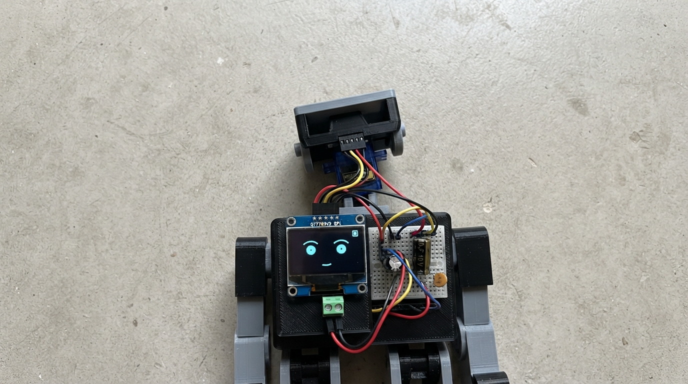
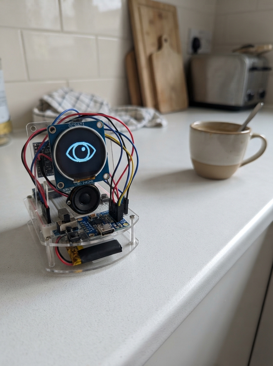
The Desk AI Buddy Robot is an expressive desktop companion built around an ESP32 microcontroller that brings personality to any workspace. It features a 1.69-inch color display for an animated face with blinking eyes, dual servo motors for head movement (yaw and roll), and a clean power architecture designed for stable operation without noise interference.
This guide provides everything needed to assemble and program the robot: a complete wiring diagram showing the display connections, servo power rail, and capacitor placement; a full parts list with specifications; Arduino firmware that animates the face and controls servo movement; and step-by-step assembly instructions covering power distribution, noise filtering, the detachable head connector, and safe ESP32 integration.
Wiring diagram

Gather all the parts
Assemble it in 8 steps
1. Mount the removable controller
Solder two socket strips to the body perfboard so the ESP32-C3 SuperMini can plug in and be removed. Place it with the USB-C connector facing an opening in the body so the cable remains accessible.
- Keep the USB-C end clear of wires and servo brackets.
- Do not apply 5 V to a pad marked 3V3; that can damage the controller.
2. Create a separate servo-power rail
Mount the 2-pin external 5 V screw terminal. Run a short thick red wire from its +5V terminal to a servo 5 V row and a short thick black wire from its GND terminal to a ground row. The external +5 V row powers only the two servos in development mode; do not connect it to the ESP32 board-power pad while USB-C is connected.
- Use a regulated 5 V supply rated for at least 2 A.
- USB-C 5 V and the external 5 V supply must not both feed the ESP32 board at the same time.
3. Fit all three servo-noise capacitors
Place the 470 µF capacitor across the external 5 V input and ground near the screw terminal. Place the 1000 µF capacitor across the same 5 V servo rail and ground beside the servo connectors. Place one 100 nF ceramic capacitor directly across 5 V and ground beside the yaw connector, and the other 100 nF ceramic capacitor directly across 5 V and ground beside the roll connector.
- For each electrolytic capacitor, its striped negative lead goes to the ground row.
- A reversed electrolytic capacitor can overheat, leak, or burst.
4. Connect the servos and common ground
Connect each SG90 red lead to the external 5 V servo rail and each brown or black lead to the common ground row. Connect the yaw orange or yellow signal lead to GPIO10 and the roll orange or yellow signal lead to GPIO3. Connect one ESP32-C3 GND pad to this same ground row.
- Keep the servo red and black wires short and thicker than their signal wires.
- Never connect an SG90 red lead to 3.3 V — that can reset or damage the controller.
- The servo supply and ESP32 must share ground or the servo signal has no reliable reference.
5. Install the safe standalone-power jumper
Fit the 2-pin removable jumper between the external 5 V rail and a dedicated wire leading to the ESP32 pad physically marked 5V, VBUS, or board power input only after you verify that exact label on your own SuperMini. Leave this jumper removed for USB-C development. For standalone operation with USB disconnected, fit the jumper so external 5 V can power the board and servos.
- A small two-pin header and shunt is easy to hand-solder and makes the safe position obvious: jumper off for USB development, jumper on only for standalone use.
- Do not fit this jumper while USB-C is powering the board unless you have separately verified a proper power-OR circuit on your exact board.
6. Build the 12-pin detachable head cable
Use matching keyed 12-pin connectors, or mark pin 1 clearly at both ends. Wire body and head positions one-to-one: 1=3V3, 2=GND, 3=SCK/GPIO4, 4=MOSI/GPIO6, 5=CS/GPIO7, 6=DC/GPIO5, 7=RST/GPIO20, 8=BLK/3V3, 9=MIC_BCLK/GPIO0, 10=MIC_WS/GPIO1, 11=MIC_DATA/GPIO21, and 12=GND/key. Pins 9 through 11 are reserved for the future microphone.
- Use a keyed plug whenever possible; otherwise use a colored pin-1 wire and label both boards.
- Keep the harness short; twisting a ground wire with nearby signal wires helps reduce noise.
- A reversed head cable can put power on a display signal and damage the display.
7. Wire the display and its local capacitor
In the lightweight head, connect the 12-pin head connector to the ST7789: pin 1 to VCC, 2 to GND, 3 to SCK, 4 to MOSI, 5 to CS, 6 to DC, 7 to RST, and 8 to BLK. Solder the third 100 nF capacitor directly between the display VCC and GND pads. Leave the reserved microphone header unpopulated until the microphone is selected.
- Only the display, its capacitor, connector, and later microphone stay in the head; the ESP32 remains in the body.
- Confirm from the actual display module markings or documentation that VCC is 3.3 V compatible before connecting it; do not apply 5 V unless the exact module explicitly supports it.
8. Check power paths before inserting the ESP32
With the ESP32 removed and the standalone-power jumper removed, apply external 5 V and measure the servo rail. Confirm it is near 5 V, the ground row is continuous, and the ESP32 board-power wire is not energized. Remove external power, insert the ESP32, then use USB-C for the first firmware deployment.
- Check for solder bridges between the 5 V rail, 3.3 V rail, and ground before powering anything.
- Stop immediately if a capacitor gets warm, the supply enters current limit, or a servo cable becomes hot.
Review all connections
1. Connections between "power_input" and "ESP32"
2. Connections between "input_bulk_cap" and "ESP32"
3. Connections between "servo_bulk_cap" and "ESP32"
4. Connections between "yaw_servo_decoupling_cap" and "ESP32"
5. Connections between "roll_servo_decoupling_cap" and "ESP32"
6. Connections between "yaw_servo" and "ESP32"
7. Connections between "roll_servo" and "ESP32"
8. Connections between "esp32_power_select" and "ESP32"
9. Connections between "body_head_header" and "ESP32"
10. Connections between "head_display_header" and "ESP32"
11. Connections between "display_decoupling_cap" and "ESP32"
12. Connections between "head_microphone_header" and "ESP32"
Deploy the firmware
#include <Arduino.h>
#include <SPI.h>
#include <Adafruit_GFX.h>
#include <Adafruit_ST7789.h>
#include <ESP32Servo.h>

constexpr int TFT_SCK_PIN = 4;
constexpr int TFT_MOSI_PIN = 6;
constexpr int TFT_CS_PIN = 7;
constexpr int TFT_DC_PIN = 5;
constexpr int TFT_RST_PIN = 20;
constexpr int YAW_SERVO_PIN = 10;
constexpr int ROLL_SERVO_PIN = 3;

Adafruit_ST7789 tft(TFT_CS_PIN, TFT_DC_PIN, TFT_RST_PIN);
Servo yawServo;
Servo rollServo;

int yawAngle = 90;
int rollAngle = 90;
unsigned long lastFaceUpdateMs = 0;
bool eyesOpen = true;

void drawEye(int centerX, int centerY, bool open) {
  const uint16_t faceColor = ST77XX_BLACK;
  const uint16_t eyeColor = ST77XX_CYAN;
  tft.fillCircle(centerX, centerY, 34, faceColor);
  if (open) {
    tft.fillRoundRect(centerX - 20, centerY - 30, 40, 60, 18, eyeColor);
    tft.fillCircle(centerX, centerY, 12, ST77XX_BLACK);
  } else {
    tft.fillRoundRect(centerX - 24, centerY - 3, 48, 7, 3, eyeColor);
  }
}

void drawFace(bool open) {
  drawEye(70, 130, open);
  drawEye(170, 130, open);
}

void setup() {
  Serial.begin(115200);
  SPI.begin(TFT_SCK_PIN, -1, TFT_MOSI_PIN, TFT_CS_PIN);
  tft.init(240, 280);
  tft.setRotation(0);
  tft.fillScreen(ST77XX_BLACK);
  tft.setTextWrap(false);
  tft.setTextColor(ST77XX_WHITE);
  tft.setTextSize(2);
  tft.setCursor(48, 32);
  tft.print("AI BUDDY");
  drawFace(true);

  yawServo.setPeriodHertz(50);
  rollServo.setPeriodHertz(50);
  yawServo.attach(YAW_SERVO_PIN, 500, 2400);
  rollServo.attach(ROLL_SERVO_PIN, 500, 2400);
  yawServo.write(yawAngle);
  rollServo.write(rollAngle);
}

void loop() {
  const unsigned long now = millis();
  if (now - lastFaceUpdateMs >= 3000) {
    lastFaceUpdateMs = now;
    eyesOpen = !eyesOpen;
    drawFace(eyesOpen);
  }
}
Remix this project
Make it yours in one click
Open a full copy of this project in your own Schematik workspace — diagram, code, parts, and assembly steps included. Swap the sensor, add features, or redesign the whole thing with AI. The author's original stays untouched.