Community project
Smart Glove Motion Schematic
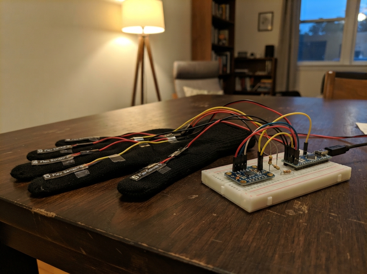
This smart glove project combines five flex sensors with a 6-axis motion sensor to capture hand gestures and arm movements. The flex sensors track individual finger bending while the MPU-6050 accelerometer and gyroscope measure wrist rotation and acceleration, enabling gesture recognition and motion-based control applications.
This guide provides a complete wiring diagram, parts list, and step-by-step assembly instructions for building the sensor array on an ESP32 microcontroller. The included firmware reads all sensor inputs and outputs the data over serial, giving makers a foundation for developing custom gesture recognition or motion control systems.
Wiring diagram

Gather all the parts
Assemble it in 7 steps
1. Make two shared power rails
Put the ESP32 board beside the breadboard. Run one red jumper from the ESP32 pin marked 3V3 to a red power rail. Run one black jumper from any ESP32 pin marked GND to a blue or black ground rail. All five flex sensors and the MPU6050 share these two rails.
- Use red only for 3.3 V and black only for GND. Keeping these colors consistent makes every connection easier to follow.
- Do not use the ESP32 pin marked VIN or 5V for these parts. The flex-sensor divider points and MPU6050 signals are designed around 3.3 V.
2. Wire Flex Sensor 1 — GPIO34
Make one three-way junction in a single breadboard row: Flex Sensor 1 SIG_END, ESP32 GPIO34, and the TOP leg of 10 kΩ Resistor 1 all meet in that same row. Connect Flex Sensor 1 3V3_END to the 3.3 V rail. Connect the BOTTOM leg of 10 kΩ Resistor 1 to the GND rail.
- Label this junction “Flex 1 / GPIO34” with tape or a marker. It is the exact point where the board reads finger bend.
- Do not connect GPIO34 straight to GND or straight to 3.3 V; it must connect only at the shared sensor-and-resistor junction.
3. Wire Flex Sensor 2 — GPIO35
Make one three-way junction in a new breadboard row: Flex Sensor 2 SIG_END, ESP32 GPIO35, and the TOP leg of 10 kΩ Resistor 2 all meet in that same row. Connect Flex Sensor 2 3V3_END to the 3.3 V rail. Connect the BOTTOM leg of 10 kΩ Resistor 2 to the GND rail.
- Label this junction “Flex 2 / GPIO35” and keep its wire separate from the GPIO34 wire.
- Each flex sensor needs its own 10 kΩ resistor; do not join the five signal junctions together.
4. Wire Flex Sensor 3 — GPIO32
Make one three-way junction in a new breadboard row: Flex Sensor 3 SIG_END, ESP32 GPIO32, and the TOP leg of 10 kΩ Resistor 3 all meet in that same row. Connect Flex Sensor 3 3V3_END to the 3.3 V rail. Connect the BOTTOM leg of 10 kΩ Resistor 3 to the GND rail.
- Label this junction “Flex 3 / GPIO32.” Arrange the sensor strips in finger order so the labels remain easy to match.
- Make sure the resistor leg shares the GPIO32 row, not the 3.3 V row.
5. Wire Flex Sensor 4 — GPIO33
Make one three-way junction in a new breadboard row: Flex Sensor 4 SIG_END, ESP32 GPIO33, and the TOP leg of 10 kΩ Resistor 4 all meet in that same row. Connect Flex Sensor 4 3V3_END to the 3.3 V rail. Connect the BOTTOM leg of 10 kΩ Resistor 4 to the GND rail.
- Label this junction “Flex 4 / GPIO33.” Use a different signal-wire color from the red and black power wires.
- Do not swap GPIO33 with a power rail; a swapped wire gives unusable bend readings.
6. Wire Flex Sensor 5 — GPIO25
Make one three-way junction in a new breadboard row: Flex Sensor 5 SIG_END, ESP32 GPIO25, and the TOP leg of 10 kΩ Resistor 5 all meet in that same row. Connect Flex Sensor 5 3V3_END to the 3.3 V rail. Connect the BOTTOM leg of 10 kΩ Resistor 5 to the GND rail.
- Label this junction “Flex 5 / GPIO25.” The five labeled rows should now all have the same shape: 3.3 V → flex sensor → GPIO junction → 10 kΩ resistor → GND.
- Keep this GPIO25 junction separate from all four other flex-sensor junctions.
7. Wire the MPU6050 motion sensor
Connect MPU6050 VIN to the 3.3 V rail (power). Connect MPU6050 GND to the GND rail (ground). Connect MPU6050 SDA to ESP32 GPIO21 (data). Connect MPU6050 SCL to ESP32 GPIO22 (clock). Leave the MPU6050 INT pin unconnected in this version.
- Run the two MPU6050 signal wires next to each other and label them SDA/GPIO21 and SCL/GPIO22. Keep them away from the five flex-sensor junction rows where possible.
- Make sure VIN and GND are not swapped — swapped power can damage the MPU6050 module.
Review all connections
1. Connections between "flex_sensor_1" and "ESP32"
2. Connections between "resistor_1" and "ESP32"
3. Connections between "flex_sensor_2" and "ESP32"
4. Connections between "resistor_2" and "ESP32"
5. Connections between "flex_sensor_3" and "ESP32"
6. Connections between "resistor_3" and "ESP32"
7. Connections between "flex_sensor_4" and "ESP32"
8. Connections between "resistor_4" and "ESP32"
9. Connections between "flex_sensor_5" and "ESP32"
10. Connections between "resistor_5" and "ESP32"
11. Connections between "mpu6050_1" and "ESP32"
Deploy the firmware
#include <Arduino.h>
#include <Wire.h>

constexpr int FLEX_1_PIN = 34;
constexpr int FLEX_2_PIN = 35;
constexpr int FLEX_3_PIN = 32;
constexpr int FLEX_4_PIN = 33;
constexpr int FLEX_5_PIN = 25;
constexpr int MPU_SDA_PIN = 21;
constexpr int MPU_SCL_PIN = 22;

void setup() {
  Serial.begin(115200);
  analogReadResolution(12);
  Wire.begin(MPU_SDA_PIN, MPU_SCL_PIN);
}

void loop() {
  const int flex1 = analogRead(FLEX_1_PIN);
  const int flex2 = analogRead(FLEX_2_PIN);
  const int flex3 = analogRead(FLEX_3_PIN);
  const int flex4 = analogRead(FLEX_4_PIN);
  const int flex5 = analogRead(FLEX_5_PIN);

  Serial.printf("Flex: %d, %d, %d, %d, %d\n", flex1, flex2, flex3, flex4, flex5);
  delay(250);
}
Remix this project
Make it yours in one click
Open a full copy of this project in your own Schematik workspace — diagram, code, parts, and assembly steps included. Swap the sensor, add features, or redesign the whole thing with AI. The author's original stays untouched.