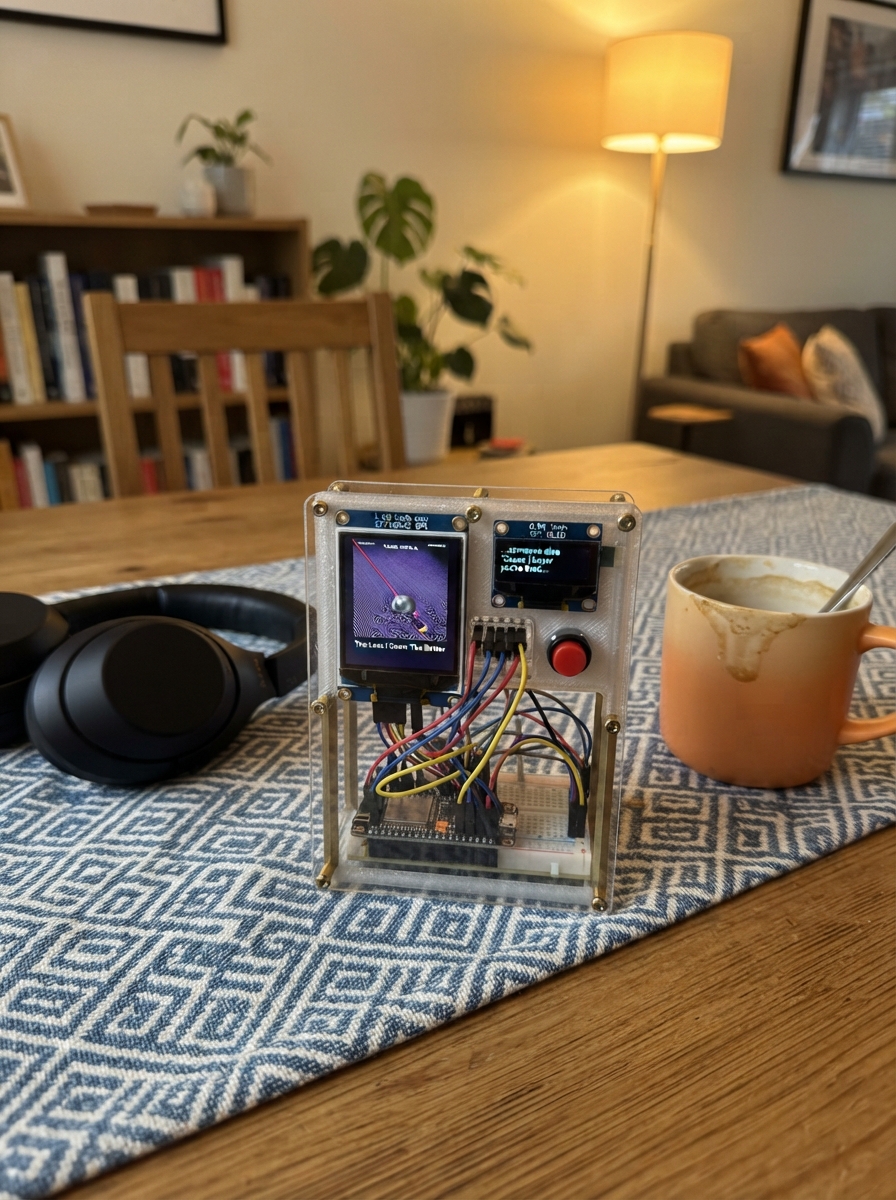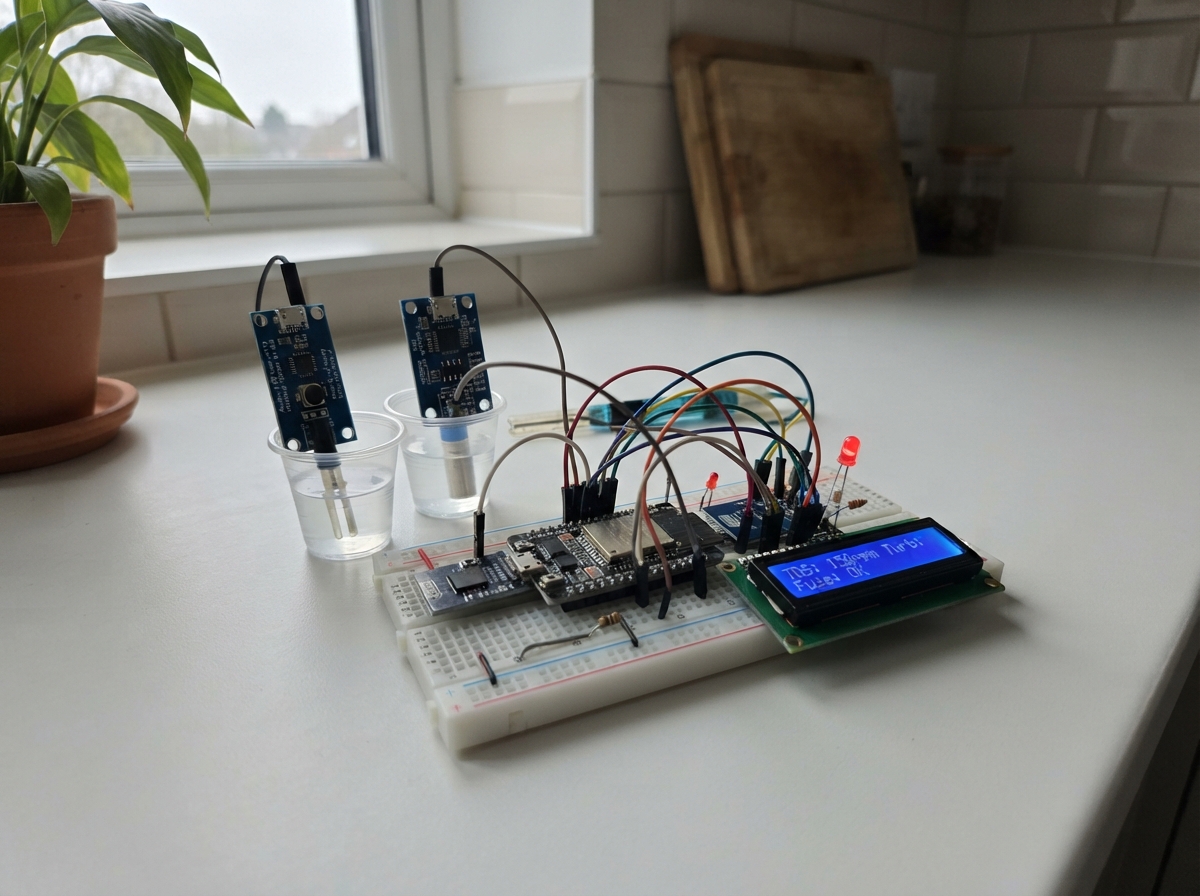
This water quality monitoring system combines a Raspberry Pi Pico with analog sensors to measure pH, turbidity, and total dissolved solids (TDS) in water samples. The project reads three sensors through analog inputs, displays live readings on an I2C LCD screen, logs data to a microSD card, and serves results over WiFi to a web dashboard for remote viewing.
Builders will receive a complete wiring diagram, parts list, calibration procedures, and step-by-step assembly instructions. The guide covers breadboard layout, sensor connection, LCD configuration at 3.3 V logic levels, and a separate battery-powered pump circuit controlled by a manual rocker switch. Firmware includes WiFi connectivity, SD card logging, pH calibration routines, and a web interface—everything needed to monitor water conditions for educational or experimental purposes.
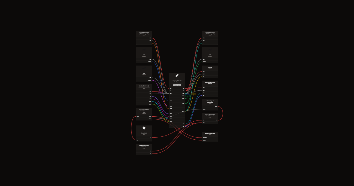
Wiring diagram
Gather all the parts
Assemble it in 7 steps
1. Prepare your RAM Electronics BB-01 breadboard
Use your exact RAM Electronics BB01.BREAD.BOARD, BB-01 / MB102 830-tie-point breadboard from https://www.ram-e-shop.com/shop/bb01-bread-board-bb-01-breadboard-830-tie-point-6143?category=6 . The on-screen breadboard uses the available generic 830-point graphic; its printed rail markings cannot be customized through these project files. Use this physical breadboard (approximately 165 × 55 mm) and a Raspberry Pi Pico 2 W with soldered headers. Place the Pico across the centre gap so its opposite header rows are not connected together. The main terminal strips connect groups of five holes on each side, not across the centre gap. With USB unplugged, orient the breadboard with its long power rails running vertically and keep the same orientation as your photo; do not rotate the breadboard. The four printed power rails are plus, minus, plus, minus (+ - + -) from left to right. Use the leftmost red plus rail for 3.3 V from 3V3 OUT (physical pin 36), the next blue minus rail for GND, the next red plus rail for USB 5 V from VBUS (physical pin 40), and the rightmost blue minus rail for GND. Join the two minus rails to a Pico GND pin. Keep the two plus rails separate; never bridge 3.3 V to 5 V. The printed colours do not electrically set polarity; use clear labels matching these assigned voltages. Before applying power, use a multimeter in continuity mode to check each rail for breaks. If a rail is split, bridge only its matching sections with a jumper; never bridge adjacent rails. Use GP numbers, not physical pin numbers, for signals. Leave the 24V supply disconnected.
- Never connect 5V sensor signals directly to Pico inputs. Keep electronics dry. Green does not mean drinking water is safe.
2. Wire three analog sensors
TDS VCC to 3V3, ground to GND, signal to GP26. Turbidity VCC to 5V and ground to GND. Its analog signal goes through a 10k resistor to GP27; another 10k goes from GP27 to GND. Set analog mode. Use a DFRobot SEN0161 pH module powered from 5V; PO goes through a 10k resistor to GP28, with another 10k from GP28 to GND. Plug probes into their respective module connectors. Each resistor pair halves the voltage to protect the Pico. Your four 10k ceramic resistors can serve here if their leads fit securely; otherwise use smaller 1/4W equivalents.
- The selected pH module is SEN0161; other pH boards require their own calibration. Measure separate samples to check for interference between immersed probes.
3. Connect indicators and your six-pin SD adapter
GP20, GP21 and GP22 each go through their own 220 ohm resistor to the green, yellow and red LED long legs respectively. Short legs to GND. With USB unplugged, connect the RAM Electronics SD adapter VCC to VBUS (physical pin 40), GND to GND (pin 23), CS to GP17 (pin 22), SCK to GP18 (pin 24), MOSI to GP19 (pin 25), and MISO to GP16 (pin 21). VCC is the terminal label; VBUS supplies USB 5V. Do not connect SD VCC to 3V3 OUT. Insert a FAT32-formatted microSD or microSDHC card (up to 32GB) with power off. Logging appends readings every two seconds to WATER.CSV; timestamps are uptime, not calendar time. The dashboard sd_ok reports storage status. Leave the separate power supply disconnected. Pico 3V3 OUT still powers the TDS sensor.
- Do not substitute 0.1 ohm resistors for LED resistors. Power off before removing the card.
4. Calibrate and keep the enclosure dry
Use pH 4 and 7 buffer solutions and record the dashboard ph_voltage in each after settling. Enter those voltages as PH_V4 and PH_V7 and set PH_CALIBRATED true before relying on pH. Calibrate TDS_GAIN against a standard. TDS assumes 25C; turbidity is a voltage trend, not calibrated NTU. Keep the turbidity probe top and all module boards dry. Unspecified spare fuses, 1N4007 diodes and 0.1 ohm resistors are not substitutes for the pump protection parts listed here.
- Demonstration thresholds are not health limits. These sensors cannot detect pathogens or determine disinfection doses. Do not drink test samples.
5. Try your LCD entirely at 3.3 V
Unplug USB before rewiring. Remove the BSS138 module and all its wires. Connect LCD VCC to Pico 3V3 OUT (physical pin 36), GND to common ground, SDA to GP4 (pin 6, data), and SCL to GP5 (pin 7, clock). The LCD and its backpack must both use this same 3.3 V supply. Reconnect USB and press Deploy. Adjust the built-in contrast screw gently. Firmware automatically detects the backpack address and displays readings if initialization succeeds; monitoring continues if no LCD is detected. A detected backpack alone does not prove characters are visible.
- Experimental undervoltage operation is not guaranteed for this LCD. The screen may be blank, faint or unreliable even if the backlight or backpack works. If it fails, disconnect it and use the dashboard until proper 5 V operation with an I2C level shifter is available.
- Never move LCD VCC to VBUS or another 5 V supply while SDA and SCL are directly connected to the Pico. Do not use an external 5 V backlight supply in this setup.
- LCD values and GREEN status cannot establish drinking-water safety.
6. Build the separate battery-powered manual pump circuit
Remove all batteries and unplug USB before wiring. Use the exact Lampatronics R385 12 V inlet/outlet pump. Load the Adafruit 449 plain holder with eight identical fresh 1.5 V alkaline AA batteries only after checks. Use a two-terminal manual rocker switch explicitly rated for at least 5 A at 12 V DC motor loads. Battery positive goes to the inline MINI fuse holder input; insert the separate MIN2 2 A fuse in that holder, then holder output to switch T1; switch T2 to pump positive. Pump negative goes straight to battery negative. The fuse-to-holder lines in the diagram represent the fuse inserted into its socket, not extra external jumpers. Connect the 1N5408 across the pump: striped cathode to pump positive and unstriped anode to pump negative. Use short insulated 18 AWG connections, properly crimped or soldered and insulated, not breadboard jumpers. Keep the fuse near the battery. Check polarity with a voltmeter before connecting the pump.
- No part of this battery circuit connects to Pico pins, USB power, breadboard rails or Pico ground. Keep the 24 V supply disconnected.
- The holder supports up to 2 A peak according to its maker; exact pump startup and running current remain unverified. Confirm these against holder, cell, switch and wire ratings before sustained operation. If startup exceeds 2 A use a suitably rated protected 12 V battery system instead. Do not stall the pump to measure current; never put an ammeter directly across a battery.
- The 2 A fuse and runtime estimate are provisional. A fuse is not an exact current limiter and does not guarantee holder protection or reliable startup. Do not bypass a blown fuse; find the cause. Stop immediately for heat, smell or repeated failed starts.
7. Test the pump using its physical switch
Secure the pump outside the water and keep its motor, switch, battery and monitoring electronics dry. Fit snug hose to the marked inlet and outlet; inlet hose goes into the sample container, outlet hose goes to a test collection container. Check the actual port markings rather than guessing flow direction. Prime as required by the pump instructions. With switch OFF, install batteries. Turn ON briefly and check flow, leaks and temperature, then turn OFF. If it does not start promptly, switch OFF rather than leaving it stalled. Remove batteries when storing. The dashboard cannot turn this pump off or report its switch state. USB monitoring works separately; press Deploy after checking the existing sensor wiring.
- Do not submerge this inlet/outlet pump or run it dry. Do not block the outlet. No drinking-water compatibility or safety is established for the pump, hoses or measured samples.
- Eight NiMH cells provide only nominal 9.6 V, not this design's nominal 12 V. Never charge alkaline batteries or replace the pack with loose lithium cells.
Review all connections
1. Connections between "green" and "Raspberry Pi Pico"
2. Connections between "r_green" and "Raspberry Pi Pico"
3. Connections between "yellow" and "Raspberry Pi Pico"
4. Connections between "r_yellow" and "Raspberry Pi Pico"
5. Connections between "red" and "Raspberry Pi Pico"
6. Connections between "r_red" and "Raspberry Pi Pico"
7. Connections between "tds" and "Raspberry Pi Pico"
8. Connections between "turb" and "Raspberry Pi Pico"
9. Connections between "ph" and "Raspberry Pi Pico"
10. Connections between "turb_top" and "Raspberry Pi Pico"
11. Connections between "turb_bottom" and "Raspberry Pi Pico"
12. Connections between "ph_top" and "Raspberry Pi Pico"
13. Connections between "ph_bottom" and "Raspberry Pi Pico"
14. Connections between "sd" and "Raspberry Pi Pico"
15. Connections between "lcd" and "Raspberry Pi Pico"
16. Connections between "breadboard" and "Raspberry Pi Pico"
17. Connections between "pump_battery" and "Raspberry Pi Pico"
18. Connections between "pump_fuse_holder" and "Raspberry Pi Pico"
19. Connections between "pump_fuse" and "Raspberry Pi Pico"
20. Connections between "pump_switch" and "Raspberry Pi Pico"
21. Connections between "pump" and "Raspberry Pi Pico"
22. Connections between "pump_diode" and "Raspberry Pi Pico"
Deploy the firmware
#include <Arduino.h>
#include <SPI.h>
#include <Wire.h>
#include <hd44780.h>
#include <hd44780ioClass/hd44780_I2Cexp.h>
hd44780_I2Cexp lcd;
bool lcdOK=false;
String lcdPrevious[2];
void lcdLine(byte row, String text){
 text=text.substring(0,16);while(text.length()<16)text+=" ";
 if(lcdOK && text!=lcdPrevious[row]){lcd.setCursor(0,row);lcd.print(text);lcdPrevious[row]=text;}
}
#include <SdFat.h>
#include <WiFi.h>
#include <WebServer.h>
WebServer server(80);
String live="{}";
const char* WIFI_SSID="";
const char* WIFI_PASSWORD="";
// Enter measured module voltages for pH 4 and 7, then set true.
const bool PH_CALIBRATED=false;
const float PH_V4=1.143, PH_V7=2.0;
float phValue=0;
const char PAGE[]=R"HTML(<!doctype html><meta name="viewport" content="width=device-width"><title>Raspberry Pi Water Monitor</title><h1>Raspberry Pi Pico 2 W Water Dashboard</h1><p>NOT a drinking-water safety test. Advice is rule-based, not trained AI.</p><p>Pump is independent of the Pico; no software control.</p><pre id="data">Waiting</pre><p id="advice"></p><script>setInterval(async()=>{try{let d=await(await fetch("/api/readings")).json();document.getElementById("data").textContent=JSON.stringify(d,null,2);let a="Obtain microbiological and chemical testing before drinking. ";if(!d.ph_calibrated)a+="Calibrate pH using pH 4 and 7 buffers. ";else if(d.ph<6.5||d.ph>8.5)a+="pH is outside the demonstration range: investigate the source; do not add chemicals based on this reading. ";if(d.tds_ppm_est>=300)a+="Elevated TDS: identify dissolved contaminants; boiling does not remove salts. ";if(d.turbidity_v<3.8)a+="Cloudiness trend: investigate sediment and consider appropriate filtration before any validated disinfection process. ";a+="No disinfectant dose can be calculated from these sensors. Follow local public-health guidance.";document.getElementById("advice").textContent=a;}catch(e){document.getElementById("advice").textContent="Connection lost"}},2000)</script>)HTML";
SdFat SD;
const float VREF=3.3; // Measure the actual 3.3V rail for calibration.
const float TDS_GAIN=1.0; // Adjust against a known TDS calibration solution.
const float WATER_TEMP=25.0; // Assumed, not measured.
// Demonstration thresholds only; NOT drinking-water safety limits.
const float TDS_YELLOW=300, TDS_RED=600;
const float TURB_YELLOW=3.8, TURB_RED=3.3;
const bool SD_ENABLED=true; // RAM adapter: VCC from USB VBUS; 3.3 V-compatible SPI.
bool sdOK=false; unsigned long lastRead=0, lastRetry=0;
float voltage(byte pin){
 int samples[31];analogRead(pin);delay(2);
 for(byte i=0;i<31;i++){samples[i]=analogRead(pin);delay(2);}
 for(byte i=0;i<30;i++)for(byte j=i+1;j<31;j++)if(samples[j]<samples[i]){int t=samples[i];samples[i]=samples[j];samples[j]=t;}
 return samples[15]*VREF/4095.0;
}
void setup(){
 Serial.begin(115200);
 Wire.setSDA(4);Wire.setSCL(5);Wire.begin();Wire.setClock(100000);
 lcdOK=(lcd.begin(16,2)==0);
 lcdLine(0,"Water monitor");lcdLine(1,"Not safety test");
 Serial.println(lcdOK?"LCD ready":"LCD not detected; monitoring continues");
 for(byte p=20;p<=22;p++){pinMode(p,OUTPUT);digitalWrite(p,LOW);}
 analogReadResolution(12);
 SPI.setRX(16); SPI.setTX(19); SPI.setSCK(18);
 pinMode(17,OUTPUT);digitalWrite(17,HIGH);sdOK=SD_ENABLED && SD.begin(SdSpiConfig(17, SHARED_SPI, SD_SCK_MHZ(4)));
 if(strlen(WIFI_SSID)){WiFi.mode(WIFI_STA);WiFi.begin(WIFI_SSID,WIFI_PASSWORD);unsigned long t=millis();while(WiFi.status()!=WL_CONNECTED && millis()-t<15000)delay(100);}
 if(WiFi.status()!=WL_CONNECTED){WiFi.mode(WIFI_AP);WiFi.softAPConfig(IPAddress(192,168,4,1),IPAddress(192,168,4,1),IPAddress(255,255,255,0));WiFi.softAP("WaterMonitor","WaterDemo2026");Serial.println("Dashboard: http://192.168.4.1");}else Serial.println(WiFi.localIP());
 server.on("/",[](){server.send(200,"text/html",PAGE);});
 server.on("/api/readings",[](){server.send(200,"application/json",live);});server.begin();
}
void loop(){
 server.handleClient();
 unsigned long now=millis();
 if(SD_ENABLED && !sdOK && now-lastRetry>=10000){lastRetry=now;sdOK=SD_ENABLED && SD.begin(SdSpiConfig(17, SHARED_SPI, SD_SCK_MHZ(4)));}
 if(now-lastRead<2000)return;lastRead=now;
 float tv=voltage(27)*2.0,dv=voltage(26);
 float pv=voltage(28)*2.0;
 phValue=4.0+(pv-PH_V4)*3.0/(PH_V7-PH_V4);
 float cv=dv/(1+0.02*(WATER_TEMP-25));
 float ppm=(133.42*cv*cv*cv-255.86*cv*cv+857.39*cv)*0.5*TDS_GAIN;
 bool suspect=tv<0.1 || tv>4.6 || dv>2.35 || ppm>1000 || pv<0.1 || pv>4.9 || (PH_CALIBRATED && (phValue<0 || phValue>14));
 byte state=(suspect||ppm>=TDS_RED||tv<TURB_RED || (PH_CALIBRATED && (phValue<6.0 || phValue>9.0)))?2:((ppm>=TDS_YELLOW||tv<TURB_YELLOW || (PH_CALIBRATED && (phValue<6.5 || phValue>8.5)))?1:0);
 const char* status=suspect?"CHECK":(state==0?"GREEN":state==1?"YELLOW":"RED");
 for(byte i=0;i<3;i++)digitalWrite(20+i,i==state?HIGH:LOW);
 if(sdOK){
 bool header=!SD.exists("WATER.CSV");FsFile f=SD.open("WATER.CSV",O_WRONLY | O_CREAT | O_APPEND);
 if(f){
 if(header)f.println(F("uptime_ms,tds_voltage,turbidity_voltage,tds_ppm_est,temp_c_assumed,ph_voltage,ph_est,ph_calibrated,status"));
 f.print(now);f.print(',');f.print(dv,3);f.print(',');f.print(tv,3);f.print(',');f.print(ppm,0);f.print(',');f.print(WATER_TEMP,1);f.print(',');f.print(pv,3);f.print(',');if(PH_CALIBRATED)f.print(phValue,2);f.print(',');f.print(PH_CALIBRATED);f.print(',');f.println(status);
 if(f.getWriteError())sdOK=false;f.close();
 }else sdOK=false;
 }
 lcdLine(0,"TDS:"+String(ppm,0)+" pH:"+(PH_CALIBRATED?String(phValue,1):String("--")));
 lcdLine(1,String(status)+" SD:"+(sdOK?"OK":"ERR")+" "+String(tv,1)+"V");
 Serial.print(now);Serial.print(',');Serial.print(dv,3);Serial.print(',');Serial.print(tv,3);Serial.print(',');Serial.print(ppm,0);Serial.print(',');Serial.println(status);
 live="{\"uptime_ms\":"+String(now)+",\"tds_ppm_est\":"+String(ppm,1)+",\"turbidity_v\":"+String(tv,3)+",\"ph_voltage\":"+String(pv,3)+",\"ph\":"+(PH_CALIBRATED?String(phValue,2):String("null"))+",\"ph_calibrated\":"+(PH_CALIBRATED?"true":"false")+",\"sd_ok\":"+(sdOK?"true":"false")+",\"status\":\""+status+"\"}";
}
Remix this project
Make it yours in one click
Open a full copy of this project in your own Schematik workspace, diagram, code, parts, and assembly steps included. Swap the sensor, add features, or redesign the whole thing with AI. The author's original stays untouched.
Related projects
Radar Kompas Pelacak Teman
Raspberry Pi Pico · November 12, 2026indra abee
Stratospheric Balloon Tracker
Raspberry Pi Pico · November 11, 2026Sven Letterer
ESP32 Project Ideas (copy) (copy)
Raspberry Pi Pico · November 11, 2026Lucas Soares