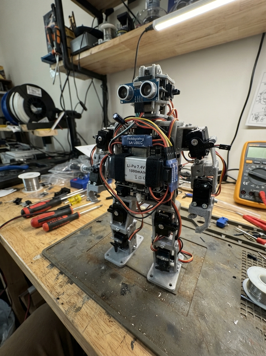
This project builds a small humanoid robot powered by an ESP32 microcontroller that walks autonomously and avoids obstacles. The robot uses six MG90D micro servos to control its hip, knee, and ankle joints on both legs, with an HC-SR04P ultrasonic sensor mounted on the front to detect nearby objects and trigger avoidance behavior.
The guide provides a complete parts list, wiring diagram, and step-by-step assembly instructions for mounting the servo joints, building the power distribution system with a 7.4V LiPo battery and UBEC regulator, and integrating the distance sensor. Firmware code handles servo control timing, obstacle detection, and walking gait generation to bring the robot to life.
Wiring diagram
Gather all the parts
Assemble it in 7 steps
1. Mount the robot joints
Fasten servo_left_hip, servo_left_knee, and servo_left_ankle into the left leg brackets, then fasten servo_right_hip, servo_right_knee, and servo_right_ankle into the matching right-leg brackets. Leave each servo horn screw out for now so the horns can be fitted after the controller has held the servos at their middle position.
- Keep the same joint order on both legs: hip at the body, knee in the middle, ankle at the foot.
- Do not force a horn onto a servo that is powered in the wrong position; forcing it can strip the small metal gears.
2. Make the battery power path
With the battery disconnected, connect battery_2s BAT+ to power_switch T1, then connect power_switch T2 to ubec_5a VIN+ (switched battery power). Connect battery_2s BAT- to ubec_5a VIN- (battery ground). Set the small selector on ubec_5a to 5.0 V before connecting anything else.
- Use insulated, thicker wire for these four power leads because the servos can draw a large brief current.
- A two-cell LiPo can deliver enough current to melt thin wire if it is shorted. Keep the switch off while making or changing connections, and charge it only with a two-cell LiPo balance charger.
3. Create the 5 V servo power rail
Join ubec_5a VOUT+ to a 5 V distribution point and join ubec_5a VOUT- to a ground distribution point. From the 5 V point, run a wire to the ESP32 VIN or 5V pin (board power) and to the red VCC wire of each of the six servos (power). From the ground point, run a wire to ESP32 GND (ground) and to the brown or black GND wire of each servo (ground).
- A small screw terminal block or a soldered power bus makes this six-way connection safer than stacking many wires into one board hole.
- Never power the six servos from the ESP32 3V3 pin or its USB connector; that can reset or damage the board. Every servo and the ESP32 must share the same ground or the position signals will not work.
4. Fit the surge capacitor
Connect the + leg of servo_capacitor to the 5 V distribution point (power) and the - leg, marked by the stripe on the capacitor body, to the ground distribution point (ground). Put it physically close to where the servo power wires meet.
- The capacitor helps prevent a brief servo tug from making the controller restart.
- The striped capacitor lead is negative. Reversing this part on the 5 V rail can make it heat up or burst.
5. Connect the six position wires
Connect the orange or yellow SIGNAL wire of servo_left_hip to ESP32 GPIO13 (left hip signal), servo_left_knee to GPIO14 (left knee signal), servo_left_ankle to GPIO16 (left ankle signal), servo_right_hip to GPIO17 (right hip signal), servo_right_knee to GPIO18 (right knee signal), and servo_right_ankle to GPIO19 (right ankle signal).
- Label both ends of each signal wire before routing it through the robot body; identical servo leads are easy to mix up.
- Do not swap a servo signal lead with its red power lead; the red wire belongs only on the 5 V distribution point.
6. Add the front distance sensor
Mount range_sensor facing forward at the robot chest. Connect VCC to ESP32 3V3 (power), GND to ESP32 GND (ground), TRIG to GPIO27 (signal), and ECHO to GPIO26 (signal). Use the 3.3 V-compatible HC-SR04P version specified here, not a common 5 V-only HC-SR04.
- Keep the two round sensor openings unobstructed and facing level with the floor.
- A 5 V-only ultrasonic sensor can send a 5 V ECHO signal into the ESP32 and damage its input; use the HC-SR04P or add a proper level shifter.
7. Center the horns and finish the frame
Keep the robot lifted so its feet cannot push against the table. Plug the ESP32 into USB, press Deploy in Schematik to load the program, then turn on the robot battery power. The servos move to their middle position first; fit the horns so both legs are straight and the feet are level, then install the horn screws.
- First test with the robot held above the table. Put it down only after all six joints move freely and the power wires stay cool.
- Keep fingers clear of the joints when battery power is on; a servo can move suddenly. Turn the switch off before moving any wire or changing a horn.
Review all connections
1. Connections between "battery_2s" and "ESP32"
2. Connections between "power_switch" and "ESP32"
3. Connections between "ubec_5a" and "ESP32"
4. Connections between "servo_left_hip" and "ESP32"
5. Connections between "servo_left_knee" and "ESP32"
6. Connections between "servo_left_ankle" and "ESP32"
7. Connections between "servo_right_hip" and "ESP32"
8. Connections between "servo_right_knee" and "ESP32"
9. Connections between "servo_right_ankle" and "ESP32"
10. Connections between "range_sensor" and "ESP32"
11. Connections between "servo_capacitor" and "ESP32"
Deploy the firmware
#include <Arduino.h>
#include <ESP32Servo.h>

constexpr int LEFT_HIP_PIN = 13;
constexpr int LEFT_KNEE_PIN = 14;
constexpr int LEFT_ANKLE_PIN = 16;
constexpr int RIGHT_HIP_PIN = 17;
constexpr int RIGHT_KNEE_PIN = 18;
constexpr int RIGHT_ANKLE_PIN = 19;
constexpr int SONAR_TRIG_PIN = 27;
constexpr int SONAR_ECHO_PIN = 26;

constexpr int CLEAR_DISTANCE_CM = 35;
constexpr unsigned long RANGE_INTERVAL_MS = 120;
constexpr unsigned long POSE_INTERVAL_MS = 450;

Servo leftHip;
Servo leftKnee;
Servo leftAnkle;
Servo rightHip;
Servo rightKnee;
Servo rightAnkle;

unsigned long lastRangeMs = 0;
unsigned long lastPoseMs = 0;
int distanceCm = 400;
bool safeToMove = false;
uint8_t pose = 0;

void setPose(int leftHipAngle, int leftKneeAngle, int leftAnkleAngle,
             int rightHipAngle, int rightKneeAngle, int rightAnkleAngle) {
  leftHip.write(leftHipAngle);
  leftKnee.write(leftKneeAngle);
  leftAnkle.write(leftAnkleAngle);
  rightHip.write(rightHipAngle);
  rightKnee.write(rightKneeAngle);
  rightAnkle.write(rightAnkleAngle);
}

int readDistanceCm() {
  digitalWrite(SONAR_TRIG_PIN, LOW);
  delayMicroseconds(3);
  digitalWrite(SONAR_TRIG_PIN, HIGH);
  delayMicroseconds(10);
  digitalWrite(SONAR_TRIG_PIN, LOW);

  unsigned long echoUs = pulseIn(SONAR_ECHO_PIN, HIGH, 30000);
  if (echoUs == 0) {
    return 400;
  }
  return static_cast<int>(echoUs / 58UL);
}

void standStill() {
  setPose(90, 90, 90, 90, 90, 90);
}

void takeInPlaceStep() {
  if (pose == 0) {
    setPose(78, 105, 92, 102, 78, 88);
  } else if (pose == 1) {
    setPose(96, 82, 88, 84, 102, 92);
  } else if (pose == 2) {
    setPose(102, 78, 88, 78, 105, 92);
  } else {
    setPose(84, 102, 92, 96, 82, 88);
  }
  pose = (pose + 1) % 4;
}

void setup() {
  Serial.begin(115200);
  pinMode(SONAR_TRIG_PIN, OUTPUT);
  pinMode(SONAR_ECHO_PIN, INPUT);
  digitalWrite(SONAR_TRIG_PIN, LOW);

  leftHip.setPeriodHertz(50);
  leftKnee.setPeriodHertz(50);
  leftAnkle.setPeriodHertz(50);
  rightHip.setPeriodHertz(50);
  rightKnee.setPeriodHertz(50);
  rightAnkle.setPeriodHertz(50);

  leftHip.attach(LEFT_HIP_PIN, 500, 2400);
  leftKnee.attach(LEFT_KNEE_PIN, 500, 2400);
  leftAnkle.attach(LEFT_ANKLE_PIN, 500, 2400);
  rightHip.attach(RIGHT_HIP_PIN, 500, 2400);
  rightKnee.attach(RIGHT_KNEE_PIN, 500, 2400);
  rightAnkle.attach(RIGHT_ANKLE_PIN, 500, 2400);

  standStill();
  delay(800);
}

void loop() {
  unsigned long now = millis();

  if (now - lastRangeMs >= RANGE_INTERVAL_MS) {
    lastRangeMs = now;
    distanceCm = readDistanceCm();
    safeToMove = distanceCm >= CLEAR_DISTANCE_CM;
    Serial.printf("Range: %d cm, %s\n", distanceCm, safeToMove ? "moving" : "paused");

    if (!safeToMove) {
      pose = 0;
      standStill();
    }
  }

  if (safeToMove && now - lastPoseMs >= POSE_INTERVAL_MS) {
    lastPoseMs = now;
    takeInPlaceStep();
  }

  delay(1);
}
Download project files
Remix this project
Make it yours in one click
Open a full copy of this project in your own Schematik workspace, diagram, code, parts, and assembly steps included. Swap the sensor, add features, or redesign the whole thing with AI. The author's original stays untouched.