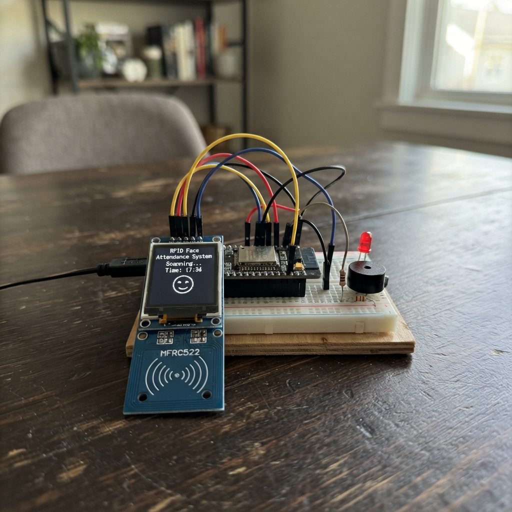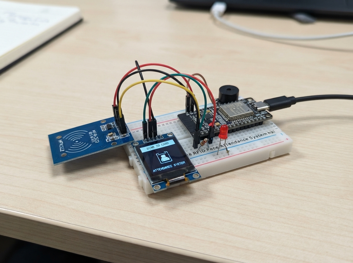
This RFID face attendance system combines card-based identification with visual verification using an ESP32-S3 microcontroller and OV2640 camera module. The system reads RFID cards through an MFRC522 module, displays status on a compact ST7735 screen, and provides audio feedback via a piezo buzzer while capturing attendance records.
The guide includes a complete wiring diagram connecting the RFID reader, display, buzzer, and indicator LED to the ESP32-S3, a full parts list with specifications, firmware code for both the attendance controller and camera node, and step-by-step assembly instructions. Builders will learn how to configure the modular firmware, set up WiFi communication between controllers, and integrate camera capture with RFID card verification.
Wiring diagram
Gather all the parts
Assemble it in 6 steps
1. Disconnect USB before wiring
With all power unplugged, connect ESP32-CAM 5V to the DevKitC pin marked 5V0 (the 5V/VIN supply input), and ESP32-CAM GND to DevKitC GND. Power the ESP32-CAM 5V pin from a regulated 5V supply (allow at least 1A for both boards); the ESP32-CAM has no USB socket, so use a suitable ESP32-CAM USB programming base or 3.3V-logic USB-to-serial adapter for programming; leave both DevKitC USB sockets unplugged during shared-power operation. Do not connect the 3V3 pins together. The diagram endpoint VIN is the physical DevKitC 5V0 pin. Camera data still travels over Wi-Fi through the server. DevKitC sends card requests to the PC, the PC fetches ESP32-CAM images and returns the result. Leave TX/RX serial pins unconnected; this firmware does not use a serial link between boards.
- Before deploying to the DevKitC by USB, unplug all power and remove the 5V jumper. Deploy with DevKitC USB connected, then unplug it before restoring the jumper. Never connect DevKitC USB power and the shared 5V jumper together.
- If either board resets during Wi-Fi or camera capture, disconnect the jumper and return to separate USB supplies. The regulated 5V supply must supply both boards and all modules.
2. Connect the shared screen and card bus
Connect RC522 SCK and screen SCK to GPIO12 (clock). Connect RC522 MOSI and screen SDA to GPIO11 (data). RC522 MISO goes to GPIO13, SDA to GPIO10 (select), RST to GPIO14. Screen CS goes to GPIO15, A0/DC to GPIO16, RESET to GPIO17. Both VCC pins go to 3V3 and both GND pins to GND. Leave RC522 IRQ unused.
- Connect DevKitC 5V0 through the 100 ohm resistor to screen LED (backlight power). Keep screen VCC on 3V3. Do not bypass the resistor because this module has no confirmed onboard backlight current limiting or direct-5V rating. The screen is assumed to be 128 by 160 pixels with black-tab initialization.
- Never power RC522 from 5V.
3. Connect the low-current active piezo buzzer
With power unplugged, connect buzzer plus to DevKitC GPIO7 (beep output) and buzzer minus to DevKitC GND. GPIO7 HIGH sounds the buzzer. No transistor, base resistors or diode are used. Existing firmware beep timing is unchanged.
- Direct wiring requires a 3.3V active piezo buzzer rated at no more than 5 mA. Check its specifications before powering it. A buzzer sounding correctly does not confirm safe current. Do not directly connect an unknown-current or magnetic buzzer; those require a driver.
4. Add one resistor per indicator
GPIO4 to the green 330 ohm resistor then green LED long leg. GPIO5 to the yellow resistor then yellow LED long leg. GPIO6 to the red resistor then red LED long leg. All short legs go to GND. Clear LED bodies do not identify their colour; test each one through its resistor.
5. Position the camera
With all power unplugged, seat the OV2640 ribbon fully in the ESP32-CAM camera socket and close its latch. The OV2640 connects through this ribbon, not through jumper wires. Mount the camera at face height with even front lighting. Keep card-reader wiring short and away from the camera ribbon.
6. Keep firmware roles separate
Set Wi-Fi credentials and the server key in include/config.h before Deploy. The selected build is AI Thinker ESP32-CAM camera firmware. Deploy only to the ESP32-CAM, not the DevKitC. For a manual serial adapter, connect adapter TX to U0R/GPIO3, RX to U0T/GPIO1 and GND to GND, with 3.3V signal levels. Connect GPIO0 to GND and reset for upload; remove the GPIO0 jumper and reset after upload. Use only one 5V power source; do not join two powered 5V outputs. Never use the pin marked 3.3V/5V (VCC output) as the 5V input; use the pin explicitly marked 5V. The DevKitC keeps its existing firmware. All restored module GPIO connections belong to the DevKitC, not the ESP32-CAM. No upload is needed just to restore this diagram.
Review all connections
1. Connections between "rfid" and "ESP32"
2. Connections between "screen" and "ESP32"
3. Connections between "r_bl" and "ESP32"
4. Connections between "r_green" and "ESP32"
5. Connections between "green" and "ESP32"
6. Connections between "r_yellow" and "ESP32"
7. Connections between "yellow" and "ESP32"
8. Connections between "r_red" and "ESP32"
9. Connections between "red" and "ESP32"
10. Connections between "terminal" and "ESP32"
11. Connections between "buzzer" and "ESP32"
Deploy the firmware
// Diagram restored: external modules remain on the separate DevKitC; camera uses the AI Thinker OV2640 mapping.
#include <Arduino.h>
#include <WiFi.h>
#include <HTTPClient.h>
#include "config.h"
#if CAMERA_NODE
#include "esp_camera.h"
#include <WebServer.h>
// AI Thinker OV2640 ribbon mapping; PWDN is active HIGH; esp_camera_init handles power-up. Reset is not connected.
WebServer web(80);
bool ready=false;
void setup(){
 Serial.begin(115200);
 camera_config_t c={};
 c.ledc_channel=LEDC_CHANNEL_0;c.ledc_timer=LEDC_TIMER_0;
 c.pin_d0=5;c.pin_d1=18;c.pin_d2=19;c.pin_d3=21;c.pin_d4=36;c.pin_d5=39;c.pin_d6=34;c.pin_d7=35;
 c.pin_xclk=0;c.pin_pclk=22;c.pin_vsync=25;c.pin_href=23;
 c.pin_sccb_sda=26;c.pin_sccb_scl=27;c.pin_pwdn=32;c.pin_reset=-1;
 c.xclk_freq_hz=20000000;c.pixel_format=PIXFORMAT_JPEG;c.frame_size=FRAMESIZE_VGA;
 c.jpeg_quality=10;c.fb_count=1;c.fb_location=CAMERA_FB_IN_PSRAM;c.grab_mode=CAMERA_GRAB_WHEN_EMPTY;
 ready=psramFound() && esp_camera_init(&c)==ESP_OK;
 if(ready){auto s=esp_camera_sensor_get();s->set_hmirror(s,1);s->set_vflip(s,0);s->set_brightness(s,1);s->set_saturation(s,0);s->set_ae_level(s,-3);}
 else Serial.println("Camera failed: check ribbon, OV2640 connection and PSRAM");
 WiFi.begin(WIFI_SSID,WIFI_PASSWORD);
 const char* headers[]={"X-Key"};web.collectHeaders(headers,1);
 web.on("/capture",HTTP_GET,[]{
  if(String(API_KEY).startsWith("CHANGE_ME") || web.header("X-Key")!=API_KEY){web.send(403);return;}
  if(!ready){web.send(503);return;}
  // Discard old buffered frame so this photograph belongs to the current request.
  auto old=esp_camera_fb_get();if(old)esp_camera_fb_return(old);
  auto f=esp_camera_fb_get();if(!f){web.send(503);return;}
  web.sendHeader("Cache-Control","no-store");web.setContentLength(f->len);web.send(200,"image/jpeg","");
  auto client=web.client();size_t sent=0;unsigned long start=millis();
  while(sent<f->len && client.connected() && millis()-start<5000){size_t n=client.write(f->buf+sent,min((size_t)1460,f->len-sent));if(!n)break;sent+=n;}
  esp_camera_fb_return(f);
 });web.begin();
}
void loop(){web.handleClient();static bool shown=false;if(WiFi.status()==WL_CONNECTED&&!shown){Serial.println(WiFi.localIP());shown=true;}delay(2);}

#endif
Remix this project
Make it yours in one click
Open a full copy of this project in your own Schematik workspace, diagram, code, parts, and assembly steps included. Swap the sensor, add features, or redesign the whole thing with AI. The author's original stays untouched.