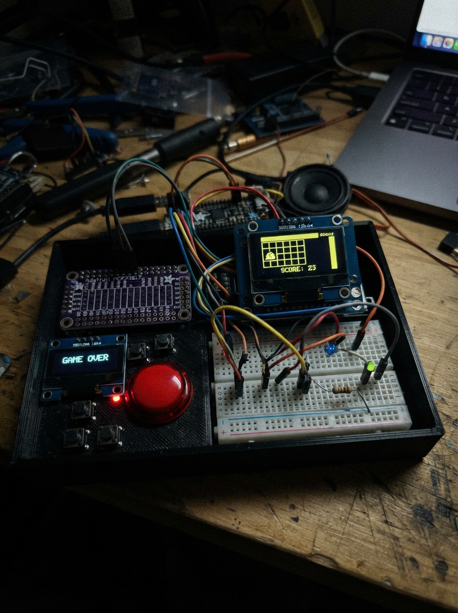
Build a whack-a-mole game on the ESP32 that lights up nine LEDs in random sequence while players race to press buttons before time runs out. The game displays the countdown and remaining time on one OLED screen while a second screen shows the final score, creating an engaging arcade-style experience.
This guide provides a complete wiring diagram, parts list, and firmware to get the game running. Assembly covers connecting the MCP23017 I/O expander for button inputs, wiring nine LED outputs, configuring both SSD1306 displays on separate I2C buses, and testing the finished circuit. Makers will have everything needed to assemble and program a fully functional two-screen game system.
Wiring diagram
Gather all the parts
Assemble it in 5 steps
1. Arrange the game
Unplug USB. Arrange nine red LEDs and nine buttons as matching pairs in a 3 by 3 grid, numbered left to right, top to bottom. Place the Start button separately. Use an ESP32 DevKit v1 and the Adafruit MCP23017 breakout 5346, not a bare chip.
2. Connect the button expander
Connect VIN to 3V3, GND to GND, RST to 3V3, SDA to GPIO21 (data) and SCL to GPIO22 (clock). Leave all three address jumpers open for address 0x20. Buttons 1–7 connect to A0–A6; buttons 8 and 9 connect to B0 and B1; Start connects to B2. Each button's other contact goes to GND. Internal pullups keep unpressed inputs high.
- Do not use A7 or B7 as button inputs. On four-leg switches, use contacts on opposite switching sides, not two permanently joined legs.
3. Wire the nine lights
LEDs 1–9 use GPIO4, 13, 14, 16, 17, 18, 19, 23 and 25 respectively. Each GPIO goes through its own 330 ohm resistor to the LED's long positive leg. Connect every short negative leg to GND.
- Never connect an LED directly to a GPIO without its resistor.
4. Connect both screens
Use two 128x64 four-pin SSD1306 I2C OLED modules at their default 0x3C address. Both VCC pins go to 3V3 and both GND pins go to GND. Game screen SDA goes to GPIO21 (data) and SCL to GPIO22 (clock). Score screen SDA goes to GPIO32 (data) and SCL to GPIO33 (clock). Separate ESP32 I2C controllers let both screens keep the same address. Use OLED modules with onboard I2C pullups.
- Check the printed VCC and GND labels; header order varies. Power everything from 3.3V, not 5V.
5. Inspect the finished circuit
Check every ground and resistor, and make sure there are no shorts between 3V3 and GND. Start begins the 3, 2, 1, Go! sequence. During the 30-second round, press the button matching the lit LED for one point. Wrong buttons do not score. Each target lasts up to one second. Holding a button does not repeat points. Start works again after Game Over.
Review all connections
1. Connections between "io" and "ESP32"
2. Connections between "game" and "ESP32"
3. Connections between "score" and "ESP32"
4. Connections between "button1" and "ESP32"
5. Connections between "button2" and "ESP32"
6. Connections between "button3" and "ESP32"
7. Connections between "button4" and "ESP32"
8. Connections between "button5" and "ESP32"
9. Connections between "button6" and "ESP32"
10. Connections between "button7" and "ESP32"
11. Connections between "button8" and "ESP32"
12. Connections between "button9" and "ESP32"
13. Connections between "start" and "ESP32"
14. Connections between "r1" and "ESP32"
15. Connections between "led1" and "ESP32"
16. Connections between "r2" and "ESP32"
17. Connections between "led2" and "ESP32"
18. Connections between "r3" and "ESP32"
19. Connections between "led3" and "ESP32"
20. Connections between "r4" and "ESP32"
21. Connections between "led4" and "ESP32"
22. Connections between "r5" and "ESP32"
23. Connections between "led5" and "ESP32"
24. Connections between "r6" and "ESP32"
25. Connections between "led6" and "ESP32"
26. Connections between "r7" and "ESP32"
27. Connections between "led7" and "ESP32"
28. Connections between "r8" and "ESP32"
29. Connections between "led8" and "ESP32"
30. Connections between "r9" and "ESP32"
31. Connections between "led9" and "ESP32"
Deploy the firmware
#include <Arduino.h>
#include <Wire.h>
#include <Adafruit_GFX.h>
#include <Adafruit_SSD1306.h>
#include <Adafruit_MCP23X17.h>
#include <esp_system.h>
TwoWire scoreBus(1);
Adafruit_SSD1306 game(128,64,&Wire,-1), points(128,64,&scoreBus,-1);
Adafruit_MCP23X17 io;
const uint8_t leds[]={4,13,14,16,17,18,19,23,25};
const uint8_t keys[]={0,1,2,3,4,5,6,8,9,10};
struct Button { bool raw=false,down=false; uint32_t changed=0; } buttons[10];
enum State {READY,COUNT,PLAY,OVER};
State state=READY;
uint32_t phaseAt=0,playAt=0,moleAt=0;
int countdown=3,score=0,target=-1,lastSeconds=-1;
bool dirty=true,scoreDirty=true;
void lightsOff(){for(auto p:leds)digitalWrite(p,LOW);target=-1;}
void nextMole(uint32_t now){int old=target;lightsOff();do {target=esp_random()%9;}while(target==old);digitalWrite(leds[target],HIGH);moleAt=now;}
void render(int seconds){
 if(dirty){
  game.clearDisplay();game.setTextColor(SSD1306_WHITE);game.setCursor(0,0);
  if(state==READY){game.setTextSize(3);game.println("Start");game.setTextSize(1);game.println("Press START button");}
  else if(state==COUNT){game.setTextSize(4);if(countdown)game.print(countdown);else game.print("Go!");}
  else if(state==PLAY){game.setTextSize(2);game.println("Time left");game.setTextSize(3);game.print(seconds);game.setTextSize(1);game.println(" seconds");}
  else {game.setTextSize(2);game.println("Game Over");game.setTextSize(1);game.print("Score: ");game.println(score);game.println();game.println("Press START to replay");}
  game.display();dirty=false;
 }
 if(scoreDirty){points.clearDisplay();points.setTextColor(SSD1306_WHITE);points.setCursor(0,0);points.setTextSize(2);points.println("Score");points.setTextSize(3);points.println(score);points.display();scoreDirty=false;}
}
void setup(){
 Serial.begin(115200);
 for(auto p:leds){pinMode(p,OUTPUT);digitalWrite(p,LOW);}
 Wire.begin(21,22);scoreBus.begin(32,33);
 if(!io.begin_I2C(0x20,&Wire)||!game.begin(SSD1306_SWITCHCAPVCC,0x3C,true,false)||!points.begin(SSD1306_SWITCHCAPVCC,0x3C,true,false)){
  Serial.println("Initialization failed: check displays and expander wiring.");while(true)delay(100);
 }
 // A7 and B7 remain outputs: these pins must not be used as inputs.
 io.pinMode(7,OUTPUT);io.digitalWrite(7,LOW);io.pinMode(15,OUTPUT);io.digitalWrite(15,LOW);
 for(auto k:keys)io.pinMode(k,INPUT_PULLUP);
 render(30);
}
void loop(){
 uint32_t now=millis();bool pressed[10]={};uint16_t raw=io.readGPIOAB();
 for(int i=0;i<10;i++){
  bool down=!(raw&(1<<keys[i]));auto &b=buttons[i];
  if(down!=b.raw){b.raw=down;b.changed=now;}
  if(now-b.changed>=25 && b.down!=b.raw){b.down=b.raw;pressed[i]=b.down;}
 }
 if((state==READY||state==OVER)&&pressed[9]){score=0;scoreDirty=true;state=COUNT;countdown=3;phaseAt=now;dirty=true;lightsOff();}
 if(state==COUNT && now-phaseAt>=1000){phaseAt=now;if(countdown>0){countdown--;dirty=true;}else{state=PLAY;playAt=now;lastSeconds=-1;nextMole(now);dirty=true;}}
 int seconds=30;
 if(state==PLAY){
  uint32_t elapsed=now-playAt;
  if(elapsed>=30000){state=OVER;lightsOff();dirty=true;seconds=0;}
  else{
   seconds=(30000-elapsed+999)/1000;
   if(seconds!=lastSeconds){lastSeconds=seconds;dirty=true;}
   if(target>=0 && pressed[target]){score++;scoreDirty=true;nextMole(now);}
   else if(now-moleAt>=1000)nextMole(now);
  }
 }
 render(seconds);delay(2);
}
Remix this project
Make it yours in one click
Open a full copy of this project in your own Schematik workspace, diagram, code, parts, and assembly steps included. Swap the sensor, add features, or redesign the whole thing with AI. The author's original stays untouched.