Community project
ESP32 Multi-Tool Gadget
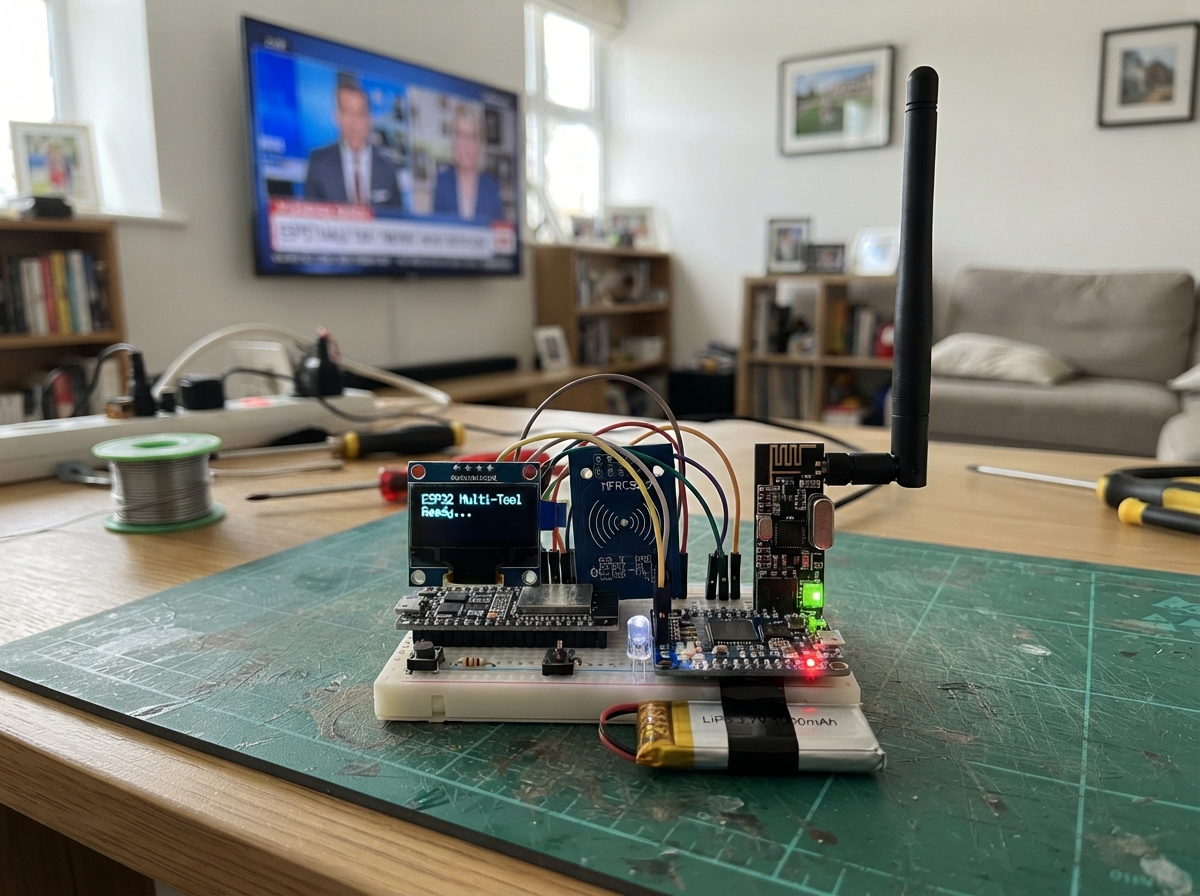
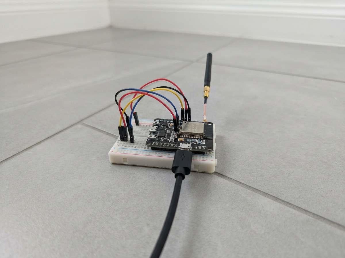
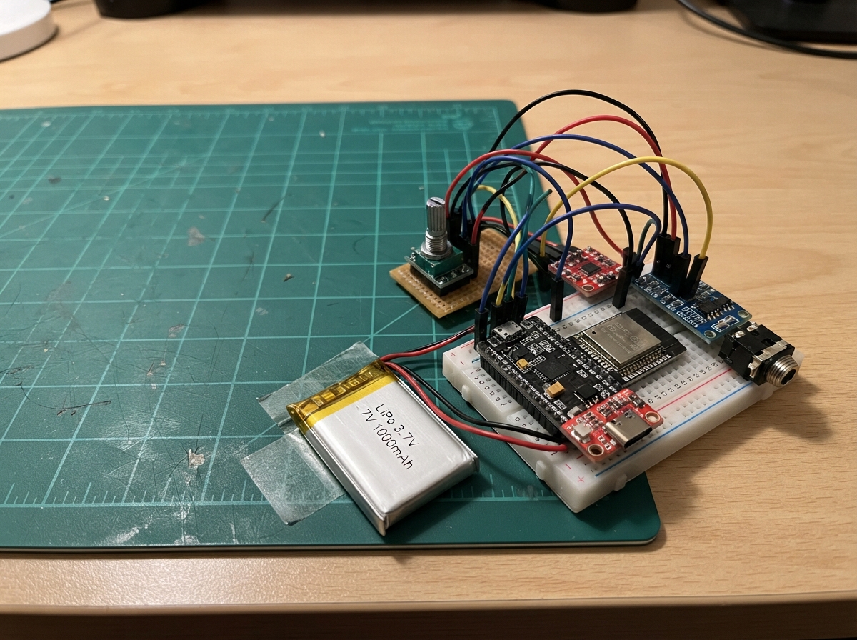
This ESP32-based multi-tool combines wireless communication, RFID scanning, and infrared control in a single portable device. It features a 128×64 OLED display for real-time feedback, dual radio modules (nRF24L01+ and CC1101) for 2.4 GHz and sub-GHz communication, MFRC522 RFID tag reading, and a 940 nm infrared LED for remote control. The rechargeable LiPo battery with PowerBoost charging makes it ready for field use.
This guide provides a complete wiring diagram, full parts list with pinout assignments, and the Arduino firmware needed to bring all features online. Assembly steps walk through building the carrier board, installing power regulation, connecting the display and radio modules, and wiring the four-button interface and IR LED. Inspection checkpoints ensure reliable operation before final module installation.
Wiring diagram

Gather all the parts
Assemble it in 7 steps
1. Make the carrier-board layout
Use the custom PCB as a carrier board: solder female header sockets for the ESP32 DevKit, OLED, RC522, nRF24, and CC1101 modules, rather than soldering the modules permanently. Put the OLED, four buttons, IR LED, and RC522 antenna along the front edge. Place the nRF24 antenna connector and the CC1101 antenna edge at opposite outer edges of the board.
- Leave the ESP32 USB socket and the PowerBoost USB socket accessible through the case.
- Keep the RC522 flat antenna area and both radio antennas clear of copper pours, batteries, and metal case walls.
- Do not place the radio antennas against the battery or a metal enclosure — this can sharply reduce their range.
2. Fit the power parts
Keep the protected LiPo battery and PowerBoost charging module as separate real modules, then connect their output to the carrier. Connect battery positive to PowerBoost BAT (battery power) and battery negative to PowerBoost GND (ground). Connect PowerBoost 5V to the carrier VIN/5V net (power) and PowerBoost GND to the carrier GND net (ground). On the carrier, connect the AMS1117 VIN pin to the 5V net (power), GND to GND (ground), and VOUT to the radio-only 3V3 net (power).
- Make the 5V and ground traces wide, and use a large ground area on both PCB sides if your board maker supports two layers.
- Put the regulator near the nRF24 header, not beside the RC522 antenna.
- Never reverse the battery wires or use a swollen, damaged, or hot LiPo battery — it can overheat or catch fire. The AMS1117 can become warm when the nRF24 transmits.
3. Add the radio power capacitor
Solder the 100 µF capacitor beside the nRF24 header: the capacitor’s positive marked lead goes to the radio-only 3V3 net (power), and its negative striped lead goes to GND (ground).
- Keep these two capacitor leads very short; it supplies the short bursts of current the nRF24 needs.
- Use a capacitor rated 6.3 V or higher.
- The capacitor’s striped negative side must go to GND — reversing it can make the capacitor fail.
4. Wire the screen and tag reader headers
Connect OLED VCC to ESP32 3V3 (power), OLED GND to GND (ground), OLED SDA to GPIO21 (data), and OLED SCL to GPIO22 (clock). Connect RC522 VCC to ESP32 3V3 (power), RC522 GND to GND (ground), SCK to GPIO18 (clock), MOSI to GPIO23 (data to reader), MISO to GPIO19 (data from reader), SDA/SS to GPIO4 (reader select), and RST to GPIO27 (reset signal).
- Label each header on the PCB with its module name and pin 1.
- The RC522 header must be on the normal ESP32 3V3 net, not the 5V net.
- Connecting the RC522 VCC pin to 5V can damage it.
5. Wire the two radio headers
All three radio-type modules share the SPI data traces: nRF24 SCK to GPIO18 (clock), MOSI to GPIO23 (data), and MISO to GPIO19 (data); nRF24 CE to GPIO17 (control) and CSN to GPIO32 (its private select). Connect CC1101 SCK to GPIO18 (clock), MOSI to GPIO23 (data), MISO to GPIO19 (data), and CSN to GPIO33 (its private select). Connect each radio VCC to the regulator’s radio-only 3V3 output (power) and each GND to GND (ground).
- Sharing SCK, MOSI, and MISO is normal; the separate CSN wires choose one module at a time.
- Use a real 433 MHz antenna on the CC1101 module and the correct antenna supplied for the nRF24 module.
- Both radio modules are 3.3 V only — connecting either VCC pin to 5V can damage it. Use radio functions only with devices, networks, and frequencies you are authorized to use.
6. Wire the buttons and infrared LED
For every push button, connect one side to GND (ground). Connect the other side of UP to GPIO13 (signal), DOWN to GPIO14 (signal), SEND to GPIO25 (signal), and BACK to GPIO26 (signal). Connect GPIO16 to one end of the 220 Ω resistor (current limiting), the other resistor end to the IR LED long leg (signal), and the LED short leg to GND (ground).
- Mount each four-leg button across a gap in the PCB footprint so a press joins two separate sides.
- A phone camera can show the IR LED flashing even though your eyes cannot see it.
- Do not omit the 220 Ω resistor — without it, excess current can damage the IR LED or ESP32 pin.
7. Inspect before fitting modules
Before plugging in the ESP32 and all module boards, inspect every solder joint and use a meter to check that the radio-only 3V3 net is not shorted to GND. Then plug the modules into the labels that match each header, keeping every antenna outward-facing.
- Power the carrier for the first time without the battery if possible, using the PowerBoost’s normal USB input.
- The first screen should show the menu. Choose Radio check and press SEND to confirm both added radio boards are physically connected.
- Do not force a header that is offset by one row — it can put power onto a signal pin and damage a module.
Review all connections
1. Connections between "oled_1" and "ESP32"
2. Connections between "rfid_1" and "ESP32"
3. Connections between "button_up" and "ESP32"
4. Connections between "button_down" and "ESP32"
5. Connections between "button_select" and "ESP32"
6. Connections between "button_back" and "ESP32"
7. Connections between "ir_resistor" and "ESP32"
8. Connections between "ir_led" and "ESP32"
9. Connections between "battery_1" and "ESP32"
10. Connections between "powerboost_1" and "ESP32"
11. Connections between "nrf24_1" and "ESP32"
12. Connections between "cc1101_1" and "ESP32"
13. Connections between "nrf24_cap" and "ESP32"
14. Connections between "radio_regulator" and "ESP32"
Deploy the firmware
#include <Arduino.h>
#include <Wire.h>
#include <SPI.h>
#include <Adafruit_GFX.h>
#include <Adafruit_SSD1306.h>
#include <MFRC522.h>
#include <IRremoteESP8266.h>
#include <IRsend.h>
#include <RF24.h>

struct ButtonState {
  uint8_t pin;
  bool previousReading;
  bool stableState;
  uint32_t changedAt;
};


// Forward declarations
bool wasPressed(ButtonState &button);
int readCc1101Version();
void drawScreen();
void scanTag();
void checkRadios();

constexpr uint8_t OLED_SDA = 21;
constexpr uint8_t OLED_SCL = 22;
constexpr uint8_t RFID_SCK = 18;
constexpr uint8_t RFID_MISO = 19;
constexpr uint8_t RFID_MOSI = 23;
constexpr uint8_t RFID_CS = 4;
constexpr uint8_t RFID_RST = 27;
constexpr uint8_t BUTTON_UP = 13;
constexpr uint8_t BUTTON_DOWN = 14;
constexpr uint8_t BUTTON_SEND = 25;
constexpr uint8_t BUTTON_BACK = 26;
constexpr uint8_t IR_LED_PIN = 16;
constexpr uint8_t NRF24_CE = 17;
constexpr uint8_t NRF24_CSN = 32;
constexpr uint8_t CC1101_CSN = 33;

constexpr uint8_t SCREEN_WIDTH = 128;
constexpr uint8_t SCREEN_HEIGHT = 64;
constexpr uint32_t NEC_TEST_CODE = 0x20DF10EF; // Change only for equipment you own.
constexpr uint8_t CC1101_VERSION_REGISTER = 0x31;

Adafruit_SSD1306 display(SCREEN_WIDTH, SCREEN_HEIGHT, &Wire, -1);
MFRC522 rfid(RFID_CS, RFID_RST);
IRsend irSender(IR_LED_PIN);
RF24 nrf24(NRF24_CE, NRF24_CSN);

ButtonState buttons[] = {
  {BUTTON_UP, HIGH, HIGH, 0},
  {BUTTON_DOWN, HIGH, HIGH, 0},
  {BUTTON_SEND, HIGH, HIGH, 0},
  {BUTTON_BACK, HIGH, HIGH, 0}
};

uint8_t menuIndex = 0;
String tagUid = "No tag scanned";
String statusLine = "Ready";
bool redrawNeeded = true;
bool nrf24Found = false;
int cc1101Version = -1;

bool wasPressed(ButtonState &button) {
  const bool reading = digitalRead(button.pin);
  const uint32_t now = millis();
  if (reading != button.previousReading) {
    button.changedAt = now;
    button.previousReading = reading;
  }
  if ((now - button.changedAt) >= 30 && reading != button.stableState) {
    button.stableState = reading;
    return button.stableState == LOW;
  }
  return false;
}

int readCc1101Version() {
  digitalWrite(CC1101_CSN, LOW);
  SPI.transfer(CC1101_VERSION_REGISTER | 0x80);
  const uint8_t version = SPI.transfer(0x00);
  digitalWrite(CC1101_CSN, HIGH);
  if (version == 0x00 || version == 0xFF) return -1;
  return version;
}

void drawScreen() {
  display.clearDisplay();
  display.setTextColor(SSD1306_WHITE);
  display.setTextSize(1);
  display.setCursor(0, 0);
  display.println(F("Pocket Remote"));
  display.drawFastHLine(0, 10, SCREEN_WIDTH, SSD1306_WHITE);

  const char *items[] = {"IR remote", "Read my tag", "Radio check"};
  for (uint8_t i = 0; i < 3; i++) {
    display.setCursor(0, 15 + (i * 9));
    display.print(menuIndex == i ? F("> ") : F("  "));
    display.println(items[i]);
  }

  display.drawFastHLine(0, 43, SCREEN_WIDTH, SSD1306_WHITE);
  display.setCursor(0, 47);
  if (menuIndex == 0) {
    display.println(F("SEND: IR test"));
  } else if (menuIndex == 1) {
    display.println(tagUid);
  } else {
    display.print(F("nRF24: "));
    display.println(nrf24Found ? F("found") : F("not found"));
  }
  display.setCursor(0, 56);
  display.println(statusLine);
  display.display();
  redrawNeeded = false;
}

void scanTag() {
  if (!rfid.PICC_IsNewCardPresent() || !rfid.PICC_ReadCardSerial()) return;
  String uid;
  for (byte i = 0; i < rfid.uid.size; i++) {
    if (rfid.uid.uidByte[i] < 0x10) uid += '0';
    uid += String(rfid.uid.uidByte[i], HEX);
    if (i + 1 < rfid.uid.size) uid += ':';
  }
  uid.toUpperCase();
  tagUid = uid;
  statusLine = "Tag read";
  rfid.PICC_HaltA();
  rfid.PCD_StopCrypto1();
  redrawNeeded = true;
}

void checkRadios() {
  nrf24Found = nrf24.begin();
  cc1101Version = readCc1101Version();
  if (cc1101Version >= 0) {
    statusLine = "CC1101 v0x" + String(cc1101Version, HEX);
    statusLine.toUpperCase();
  } else {
    statusLine = "CC1101 not found";
  }
  redrawNeeded = true;
}

void setup() {
  for (ButtonState &button : buttons) pinMode(button.pin, INPUT_PULLUP);
  pinMode(CC1101_CSN, OUTPUT);
  digitalWrite(CC1101_CSN, HIGH);

  Wire.begin(OLED_SDA, OLED_SCL);
  display.begin(SSD1306_SWITCHCAPVCC, 0x3C);
  SPI.begin(RFID_SCK, RFID_MISO, RFID_MOSI, RFID_CS);
  rfid.PCD_Init();
  irSender.begin();
  checkRadios();
}

void loop() {
  if (wasPressed(buttons[0])) {
    menuIndex = (menuIndex + 2) % 3;
    statusLine = "Menu changed";
    redrawNeeded = true;
  }
  if (wasPressed(buttons[1])) {
    menuIndex = (menuIndex + 1) % 3;
    statusLine = "Menu changed";
    redrawNeeded = true;
  }
  if (wasPressed(buttons[2])) {
    if (menuIndex == 0) {
      irSender.sendNEC(NEC_TEST_CODE, 32);
      statusLine = "IR signal sent";
      redrawNeeded = true;
    } else if (menuIndex == 1) {
      statusLine = "Hold tag near reader";
      redrawNeeded = true;
    } else {
      checkRadios();
    }
  }
  if (wasPressed(buttons[3])) {
    menuIndex = 0;
    statusLine = "Home";
    redrawNeeded = true;
  }

  if (menuIndex == 1) scanTag();
  if (redrawNeeded) drawScreen();
}
Remix this project
Make it yours in one click
Open a full copy of this project in your own Schematik workspace — diagram, code, parts, and assembly steps included. Swap the sensor, add features, or redesign the whole thing with AI. The author's original stays untouched.