Community project
ESP32 Quadcopter Flight Controller
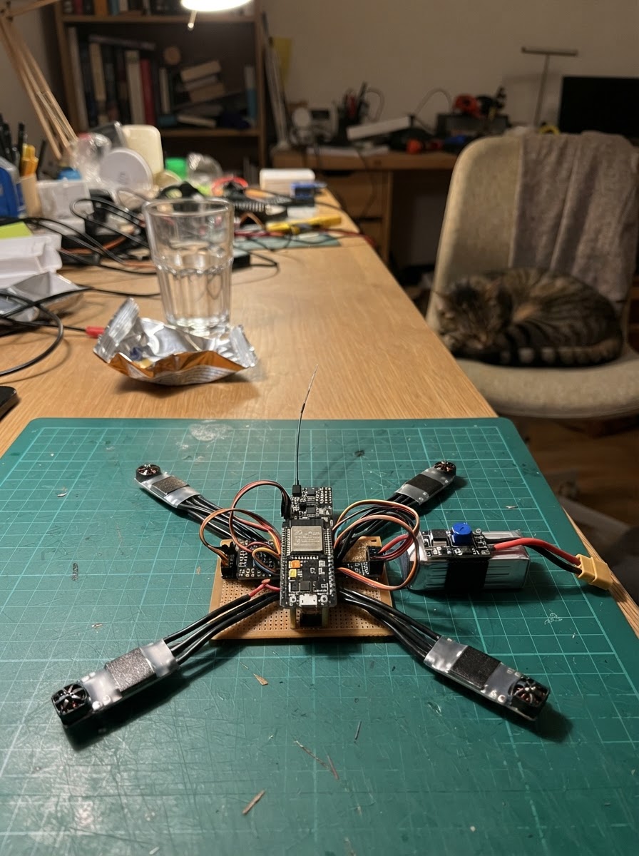
This guide builds a quadcopter flight controller around the ESP32 microcontroller, using an MPU-6050 inertial measurement unit for attitude sensing and an SBUS receiver for pilot input. Four brushless ESCs drive the motors in an X-configuration, with power regulation and safety features managed by the flight firmware.
Followers will receive a complete wiring diagram showing connections between the ESP32, MPU-6050, SBUS receiver, and four ESCs, along with a full parts list, the Arduino-based flight control firmware with gyro calibration and PID stabilization, and step-by-step assembly instructions including bench testing procedures before first flight.
Wiring diagram

Gather all the parts
Assemble it in 6 steps
1. Mount the flight electronics
With the battery unplugged, mount imu_1 rigidly near the frame center on thin vibration-damping foam. Align the sensor markings so its +X direction points to the aircraft nose and +Y points to the right. Secure the ESP32 and buck regulator away from propeller arcs and motor wiring.
- Keep the IMU level and do not let wires tug on it.
- Use short twisted signal/ground pairs for each ESC signal lead.
- Never mount or test this controller with propellers installed until motor mapping and rotation direction have been checked.
2. Wire the low-voltage controller and IMU
Connect imu_1 VIN to ESP32 3V3, GND to ESP32 GND, SDA to GPIO21, and SCL to GPIO22. Do not power this MPU6050 board from 5 V because its I2C pull-ups may then expose ESP32 GPIOs to 5 V.
- Keep the I2C leads short and away from ESC battery wires.
- ESP32 GPIO pins are 3.3 V only.
3. Prepare the regulated 5 V rail
Before connecting electronics, connect lipo_3s_1 POS to buck_5v_1 VIN and battery negative to buck_5v_1 GND. With a meter, adjust buck_5v_1 VOUT to exactly 5.0 V. Then feed this 5 V rail to the ESP32 5V/VIN pin and sbus_rx_1 VCC; connect their grounds to the common ground rail.
- Use a regulator rated for at least 1 A continuous current.
- Install an appropriate fuse between the battery and power-distribution harness.
- A 3S LiPo is 12.6 V when fully charged: never connect it directly to ESP32 5V/VIN, the receiver VCC, or the MPU6050.
- Set and verify the buck output before plugging in the ESP32.
4. Connect the receiver safely
Connect sbus_rx_1 GND to common ground and VCC to the regulated 5 V rail. Connect its SBUS output to GPIO16 only through a suitable inverter/level-shifter interface if the receiver’s SBUS output is inverted and/or above 3.3 V. Configure the transmitter so CH1=roll, CH2=pitch, CH3=throttle, CH4=yaw, and CH5 is a two-position arm switch.
- Set receiver failsafe with throttle low and arm switch OFF.
- Confirm the receiver is actually configured to emit SBUS, not PWM or another serial format.
- Do not connect a 5 V receiver data output directly to GPIO16.
5. Connect ESC signal leads
Connect esc_fl_1 SIG to GPIO25, esc_fr_1 SIG to GPIO26, esc_rl_1 SIG to GPIO27, and esc_rr_1 SIG to GPIO33. Connect every ESC SIG_GND to the ESP32/common ground. Wire each ESC’s battery leads directly to the fused 3S power-distribution harness; connect each ESC’s three motor leads to its matching motor.
- For a brushless motor, swap any two of its three ESC-to-motor wires to reverse that motor’s rotation.
- Keep ESC power current out of breadboard traces and thin jumper wires.
- Do not power the ESP32 from multiple ESC BEC outputs. Use the dedicated buck_5v_1 rail only.
- Leave all propellers removed for this entire wiring and first-power sequence.
6. Bench-test before fitting propellers
Place the frame securely on a bench with no propellers. Power on with throttle low and CH5 OFF, then use Schematik’s Deploy button. Keep the craft motionless during the 3-second gyro calibration. Confirm receiver-loss or CH5 OFF keeps all motors stopped; then check each motor position and direction at minimal throttle before any outdoor restrained test.
- If tilt correction is opposite, stop immediately and correct sensor orientation or motor mapping before attempting flight.
- Tune PID values and validate failsafe behavior in a large clear area, using a low-risk tethered test first.
- This is an experimental controller, not a certified flight-control system. Do not fly near people, roads, buildings, or restricted airspace.
- Disconnect the LiPo immediately if a motor starts unexpectedly or wiring becomes hot.
Review all connections
1. Connections between "imu_1" and "ESP32"
2. Connections between "sbus_rx_1" and "ESP32"
3. Connections between "esc_fl_1" and "ESP32"
4. Connections between "esc_fr_1" and "ESP32"
5. Connections between "esc_rl_1" and "ESP32"
6. Connections between "esc_rr_1" and "ESP32"
7. Connections between "lipo_3s_1" and "ESP32"
8. Connections between "buck_5v_1" and "ESP32"
Deploy the firmware
#include <Arduino.h>
#include <Wire.h>
#include <MPU6050.h>

// X-quad viewed from above with nose forward. MPU6050 +X faces forward, +Y right.

// Forward declarations
float clampFloat(float v, float low, float high);
float mapChannel(uint16_t v, float low, float high);
void writeEsc(uint8_t channel, uint16_t us);
void stopMotors();
void readSbus();
void calibrateGyro();

constexpr int IMU_SDA = 21;
constexpr int IMU_SCL = 22;
constexpr int SBUS_RX = 16;
constexpr int ESC_FL = 25;
constexpr int ESC_FR = 26;
constexpr int ESC_RL = 27;
constexpr int ESC_RR = 33;
constexpr uint16_t ESC_MIN_US = 1000;
constexpr uint16_t ESC_MAX_US = 2000;
constexpr uint16_t ESC_IDLE_US = 1070;
constexpr uint32_t ESC_PWM_HZ = 400;
constexpr uint32_t CONTROL_PERIOD_US = 4000;
constexpr uint32_t RX_TIMEOUT_MS = 120;
constexpr int SBUS_CENTER = 992;

MPU6050 imu;
HardwareSerial SbusSerial(2);
uint16_t rc[16] = {SBUS_CENTER};
bool sbusFailsafe = true;
bool sbusFrameLost = true;
uint32_t lastRxMs = 0;
float gyroXBias = 0.0f, gyroYBias = 0.0f;
float rollDeg = 0.0f, pitchDeg = 0.0f, rollI = 0.0f, pitchI = 0.0f;
float prevRollError = 0.0f, prevPitchError = 0.0f;
uint32_t lastControlUs = 0;
bool armed = false;

float clampFloat(float v, float low, float high) { return v < low ? low : (v > high ? high : v); }
float mapChannel(uint16_t v, float low, float high) {
  float n = clampFloat((static_cast<float>(v) - 172.0f) / 1639.0f, 0.0f, 1.0f);
  return low + n * (high - low);
}
void writeEsc(uint8_t channel, uint16_t us) {
  us = constrain(us, ESC_MIN_US, ESC_MAX_US);
  uint32_t duty = (static_cast<uint32_t>(us) * ESC_PWM_HZ * 65535UL) / 1000000UL;
  ledcWrite(channel, duty);
}
void stopMotors() { for (uint8_t i = 0; i < 4; ++i) writeEsc(i, ESC_MIN_US); }

void readSbus() {
  static uint8_t frame[25];
  static uint8_t index = 0;
  while (SbusSerial.available()) {
    uint8_t b = static_cast<uint8_t>(SbusSerial.read());
    if (index == 0 && b != 0x0F) continue;
    frame[index++] = b;
    if (index != 25) continue;
    index = 0;
    rc[0] = (frame[1] | frame[2] << 8) & 0x07FF;
    rc[1] = (frame[2] >> 3 | frame[3] << 5) & 0x07FF;
    rc[2] = (frame[3] >> 6 | frame[4] << 2 | frame[5] << 10) & 0x07FF;
    rc[3] = (frame[5] >> 1 | frame[6] << 7) & 0x07FF;
    rc[4] = (frame[6] >> 4 | frame[7] << 4) & 0x07FF;
    sbusFrameLost = frame[23] & 0x04;
    sbusFailsafe = frame[23] & 0x08;
    lastRxMs = millis();
  }
}

void calibrateGyro() {
  int32_t sx = 0, sy = 0;
  for (int i = 0; i < 600; ++i) {
    int16_t ax, ay, az, gx, gy, gz;
    imu.getMotion6(&ax, &ay, &az, &gx, &gy, &gz);
    sx += gx; sy += gy;
    delay(5);
  }
  gyroXBias = sx / 600.0f; gyroYBias = sy / 600.0f;
}

void setup() {
  Serial.begin(115200);
  Wire.begin(IMU_SDA, IMU_SCL);
  Wire.setClock(400000);
  imu.initialize();
  ledcSetup(0, ESC_PWM_HZ, 16); ledcAttachPin(ESC_FL, 0);
  ledcSetup(1, ESC_PWM_HZ, 16); ledcAttachPin(ESC_FR, 1);
  ledcSetup(2, ESC_PWM_HZ, 16); ledcAttachPin(ESC_RL, 2);
  ledcSetup(3, ESC_PWM_HZ, 16); ledcAttachPin(ESC_RR, 3);
  stopMotors();
  // SBUS: 100000 baud, 8E2, inverted. Input must be no more than 3.3 V.
  SbusSerial.begin(100000, SERIAL_8E2, SBUS_RX, -1, true);
  if (!imu.testConnection()) {
    Serial.println("MPU6050 missing: motors locked off.");
    while (true) { stopMotors(); delay(100); }
  }
  Serial.println("Hold aircraft motionless for gyro calibration.");
  calibrateGyro();
  lastControlUs = micros();
}

void loop() {
  readSbus();
  uint32_t now = micros();
  if (now - lastControlUs < CONTROL_PERIOD_US) return;
  float dt = (now - lastControlUs) / 1000000.0f;
  lastControlUs = now;
  bool receiverHealthy = (millis() - lastRxMs < RX_TIMEOUT_MS) && !sbusFailsafe && !sbusFrameLost;
  float throttle = mapChannel(rc[2], 0.0f, 1.0f);
  bool armSwitch = rc[4] > 1200;
  if (!receiverHealthy || !armSwitch) armed = false;
  else if (!armed && throttle < 0.05f) { armed = true; rollI = 0; pitchI = 0; }
  if (!armed) { stopMotors(); return; }

  int16_t ax, ay, az, gxRaw, gyRaw, gzRaw;
  imu.getMotion6(&ax, &ay, &az, &gxRaw, &gyRaw, &gzRaw);
  float gx = (gxRaw - gyroXBias) / 131.0f;
  float gy = (gyRaw - gyroYBias) / 131.0f;
  float accelRoll = atan2f(static_cast<float>(ay), static_cast<float>(az)) * 180.0f / PI;
  float accelPitch = atan2f(-static_cast<float>(ax), sqrtf(static_cast<float>(ay) * ay + static_cast<float>(az) * az)) * 180.0f / PI;
  rollDeg = 0.98f * (rollDeg + gx * dt) + 0.02f * accelRoll;
  pitchDeg = 0.98f * (pitchDeg + gy * dt) + 0.02f * accelPitch;

  float rollError = mapChannel(rc[0], -20.0f, 20.0f) - rollDeg;
  float pitchError = mapChannel(rc[1], -20.0f, 20.0f) - pitchDeg;
  rollI = clampFloat(rollI + rollError * dt, -25, 25);
  pitchI = clampFloat(pitchI + pitchError * dt, -25, 25);
  float rollOut = 5.0f * rollError + 1.2f * rollI + 0.08f * (rollError - prevRollError) / dt;
  float pitchOut = 5.0f * pitchError + 1.2f * pitchI + 0.08f * (pitchError - prevPitchError) / dt;
  prevRollError = rollError; prevPitchError = pitchError;
  float yawOut = mapChannel(rc[3], -80.0f, 80.0f);
  float base = ESC_IDLE_US + throttle * (ESC_MAX_US - ESC_IDLE_US);
  writeEsc(0, static_cast<uint16_t>(clampFloat(base + pitchOut - rollOut + yawOut, ESC_IDLE_US, ESC_MAX_US)));
  writeEsc(1, static_cast<uint16_t>(clampFloat(base + pitchOut + rollOut - yawOut, ESC_IDLE_US, ESC_MAX_US)));
  writeEsc(2, static_cast<uint16_t>(clampFloat(base - pitchOut - rollOut - yawOut, ESC_IDLE_US, ESC_MAX_US)));
  writeEsc(3, static_cast<uint16_t>(clampFloat(base - pitchOut + rollOut + yawOut, ESC_IDLE_US, ESC_MAX_US)));
}
Remix this project
Make it yours in one click
Open a full copy of this project in your own Schematik workspace — diagram, code, parts, and assembly steps included. Swap the sensor, add features, or redesign the whole thing with AI. The author's original stays untouched.
Related projects

Create A Complete Electrical Schematic Esp32 Sma
ESP32 · September 17, 2026Ayansh Agrawal
ESP32 Kare Ekran Projeleri
ESP32 · September 16, 2026Seref Ai
Component Qty --------------------------- ------
ESP32 · September 16, 2026Yathartha Chakrawal