Schematik build
ESP32 RGB Matrix Display
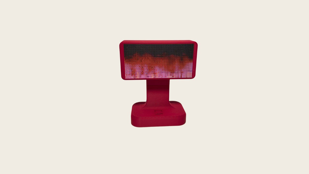
This project builds a 64x32 RGB LED matrix display driven by an ESP32 microcontroller. The display uses the HUB75 protocol, a standard interface for addressable LED panels that allows the ESP32 to control thousands of individual pixels with smooth color mixing and animation capabilities.
The guide provides a complete wiring diagram showing how to connect the HUB75 signals directly to ESP32 GPIO pins, a full parts list, and step-by-step assembly instructions. Included firmware demonstrates text rendering and pixel-level control, giving makers a foundation for building custom displays, information dashboards, or interactive art installations.
Wiring diagram

Gather all the parts
Assemble it in 4 steps
1. Identify the panel input
With all power disconnected, place the Waveshare matrix face down and locate the HUB75 connector marked IN. Use only this connector for the single 64×32 panel; do not use OUT.
- Keep the ribbon cable’s stripe and the panel’s pin-1/arrow marking aligned.
- Follow the signal labels printed on the panel instead of relying on connector orientation.
- Never connect or remove the HUB75 ribbon cable while the panel or ESP32 is powered.
2. Wire HUB75 signals directly to the ESP32
Connect the panel HUB75 IN signals directly to the ESP32: R1→GPIO25, G1→GPIO26, B1→GPIO27, R2→GPIO14, G2→GPIO13, B2→GPIO32, A→GPIO33, B→GPIO4, C→GPIO16, D→GPIO17, CLK→GPIO18, LAT→GPIO23, and OE→GPIO19. Connect every HUB75 GND pin to ESP32 GND.
- Keep the signal wiring short and label each wire.
- The 64×32 1/16-scan panel does not use HUB75 row-address E.
- This direct connection relies on the specific panel accepting 3.3 V ESP32 logic. If the display is unstable, dim, shows wrong colors, or does not respond, reinstall a proper 5 V-tolerant level buffer.
3. Connect the dedicated panel power
Connect the regulated supply’s +5 V and GND directly to the matrix panel’s dedicated power input using adequately sized wire. Connect the supply GND to ESP32 GND so the direct signal connections have a shared reference.
- Use a regulated 5 V supply rated for at least 4 A.
- Verify polarity with a multimeter before connecting the panel.
- Do not power the matrix through the ESP32 USB cable, ESP32 5 V/VIN pin, or breadboard power rails.
- Do not connect the panel’s 5 V rail to any ESP32 GPIO or 3.3 V pin.
4. Inspect before power-up
Confirm the ribbon cable is on the panel’s IN connector, all grounds are common, +5 V and GND are not reversed, and each direct GPIO connection matches the listed HUB75 label. Power the ESP32 by USB and the panel from its dedicated 5 V supply.
- The first display should read “WAVESHARE HUB75” and “ESP32 READY” with a colored line at the bottom.
- Use Schematik’s Deploy button to flash the included firmware.
- If the panel remains dark or erratic, turn off both supplies before changing wiring.
Review all connections
1. Connections between "panel_supply" and "ESP32"
2. Connections between "matrix_64x32" and "ESP32"
Deploy the firmware
#include <Arduino.h>
#include <ESP32-HUB75-MatrixPanel-I2S-DMA.h>


// Forward declarations
void drawStartupScreen();

constexpr int PANEL_RES_X = 64;
constexpr int PANEL_RES_Y = 32;
constexpr int PANEL_CHAIN = 1;

// Direct ESP32-to-HUB75 connections.
constexpr int R1_PIN = 25;
constexpr int G1_PIN = 26;
constexpr int B1_PIN = 27;
constexpr int R2_PIN = 14;
constexpr int G2_PIN = 13;
constexpr int B2_PIN = 32;
constexpr int A_PIN = 33;
constexpr int B_PIN = 4;
constexpr int C_PIN = 16;
constexpr int D_PIN = 17;
constexpr int CLK_PIN = 18;
constexpr int LAT_PIN = 23;
constexpr int OE_PIN = 19;

HUB75_I2S_CFG::i2s_pins panelPins = {
  R1_PIN, G1_PIN, B1_PIN, R2_PIN, G2_PIN, B2_PIN,
  A_PIN, B_PIN, C_PIN, D_PIN, -1,
  LAT_PIN, OE_PIN, CLK_PIN
};

HUB75_I2S_CFG matrixConfig(PANEL_RES_X, PANEL_RES_Y, PANEL_CHAIN, panelPins);
MatrixPanel_I2S_DMA *matrix = nullptr;

void drawStartupScreen() {
  matrix->fillScreen(matrix->color565(0, 0, 0));
  matrix->setTextWrap(false);
  matrix->setTextSize(1);
  matrix->setTextColor(matrix->color565(255, 60, 20));
  matrix->setCursor(1, 2);
  matrix->print("WAVESHARE HUB75");
  matrix->setTextColor(matrix->color565(30, 190, 255));
  matrix->setCursor(8, 13);
  matrix->print("ESP32 READY");

  for (int x = 0; x < PANEL_RES_X; ++x) {
    const uint16_t color = matrix->color565((x * 4) % 256, 255 - (x * 4), 120);
    matrix->drawPixelRGB565(x, 28, color);
    matrix->drawPixelRGB565(x, 29, color);
  }
}

void setup() {
  matrixConfig.clkphase = false;
  matrix = new MatrixPanel_I2S_DMA(matrixConfig);
  matrix->begin();
  matrix->setBrightness8(64);
  drawStartupScreen();
}

void loop() {
  // DMA maintains the display refresh; no redraw is necessary for this static screen.
  delay(1000);
}
Download project files
Remix this project
Make it yours in one click
Open a full copy of this project in your own Schematik workspace — diagram, code, parts, and assembly steps included. Swap the sensor, add features, or redesign the whole thing with AI. The author's original stays untouched.
Related projects
Portable RGB Animation Display
ESP32 · Intermediate · 90 minutes · July 26, 2026Schematik
WiFi LED Matrix Billboard
ESP32 · Beginner · 45 minutes · July 18, 2026Schematik
How to Build a Scrolling LED Matrix Message Board with ESP32
ESP32 · Beginner · 30 minutes · June 12, 2026Schematik