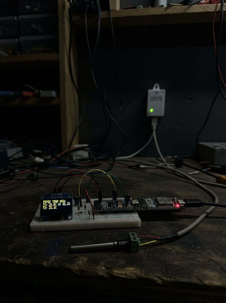
This project builds a multi-sensor temperature and humidity monitoring system using a Raspberry Pi Pico connected to Modbus RS485 temperature and humidity probes over a shared bus. The guide provides a wiring diagram, complete parts list, and step-by-step assembly instructions that keep the three probes isolated during setup before connecting them to the shared RS485 A and B lines.
The included firmware implements Modbus RTU protocol with CRC validation to read sensor data from each probe using unique addresses on the same bus. Builders will learn how to wire the SP3485 RS485 transceiver module to the Pico, configure the three sensors with different Modbus addresses, and verify all connections before powering on the complete system.
Wiring diagram
Gather all the parts
Assemble it in 6 steps
1. Keep the three probes separate at first
Do not join the three probes to the same A and B wires until they have different device addresses. This design uses address 1 for humidity probe 1, address 2 for humidity probe 2, and address 3 for the temperature probe, so the Pico can talk to one probe at a time.
- RS485 is like a shared conversation: two probes with the same address will both try to reply and the readings will fail.
- Do not connect all three probes if they all still use address 1; they can interfere with each other. Their address is normally changed using the probe supplier's configuration instructions or tool.
2. Power the RS485 converter
With the Pico W unplugged, connect the SP3485 converter VCC pin to the Pico 3V3(OUT) pin and its GND pin to any Pico GND pin. The converter must use 3.3 V because its small logic pins connect directly to the Pico.
- Use a 3.3 V SP3485 module, not the blue 5 V MAX485 board shown in the earlier photo.
- Do not put 5 V into the SP3485 VCC pin; swapped or excessive power can damage the converter.
3. Connect the Pico data wires
Connect Pico GP12 to converter TX or DI, Pico GP13 to converter RX or RO, and Pico GP14 to converter DE. Join the converter RE pin directly to its DE pin with a short jumper. GP12 sends a question, GP13 receives the reply, and GP14 chooses whether the converter is talking or listening.
- Follow the printed labels on your converter: TX means DI and RX means RO on some boards.
- Do not connect the converter TX pin to Pico GP13 or the converter RX pin to GP12; crossing these two prevents the Pico from receiving replies.
4. Make the shared A and B bus
Run one wire from converter A to the A wire of humidity probe 1, then continue that same A wire to humidity probe 2 and the temperature probe. Repeat with converter B connected to every probe B wire. Keep A with A and B with B all the way along the cable.
- For a long cable, use a twisted pair for A and B and place the probes in a chain rather than making long branches.
- Do not swap A and B at one probe; that probe will not answer. Some manufacturers reverse the A/B names, so if none answer after checking power and addresses, swap the pair together at the converter end.
5. Power all three probes
Connect each probe VCC wire to Pico VBUS, the 5 V pin supplied by USB, and connect each probe GND wire to Pico GND. All three grounds must be connected together so the signals have the same reference.
- Use a small terminal block or a power distribution strip to split the one VBUS and GND connection neatly to all three probes.
- Only use the Pico USB 5 V supply if every probe is marked 5 V. A probe marked 9–24 V, 12–24 V, or similar needs its own matching supply and must not be connected to Pico VBUS.
6. Check before switching on
Check that the SP3485 is on 3.3 V, each probe is on its marked supply voltage, every probe A joins the same A wire, every B joins the same B wire, and all grounds are joined. Then plug the Pico W into USB.
- The program prints one reading from each probe every three seconds after it is deployed.
- Never connect the blue 5 V MAX485 board's RO output directly to Pico GP13; it can put 5 V on a Pico input and damage it.
Review all connections
1. Connections between "rs485_converter" and "Raspberry Pi Pico"
2. Connections between "rs485_humidity_sensor_1" and "Raspberry Pi Pico"
3. Connections between "rs485_humidity_sensor_2" and "Raspberry Pi Pico"
4. Connections between "rs485_temperature_sensor" and "Raspberry Pi Pico"
Deploy the firmware
#include <Arduino.h>

constexpr uint8_t RS485_TX_PIN = 12;
constexpr uint8_t RS485_RX_PIN = 13;
constexpr uint8_t RS485_DIR_PIN = 14;
constexpr uint32_t MODBUS_BAUD = 9600;

// Each probe on one RS485 bus needs a different Modbus address.
constexpr uint8_t HUMIDITY_SENSOR_1_ADDRESS = 1;
constexpr uint8_t HUMIDITY_SENSOR_2_ADDRESS = 2;
constexpr uint8_t TEMPERATURE_SENSOR_ADDRESS = 3;

uint16_t modbusCrc(const uint8_t *data, size_t length) {
  uint16_t crc = 0xFFFF;
  for (size_t i = 0; i < length; ++i) {
    crc ^= data[i];
    for (uint8_t bit = 0; bit < 8; ++bit) {
      crc = (crc & 1) ? ((crc >> 1) ^ 0xA001) : (crc >> 1);
    }
  }
  return crc;
}

bool readHoldingRegisters(uint8_t address, uint16_t startRegister, uint16_t *values, uint8_t count) {
  if (count == 0 || count > 2) return false;

  uint8_t request[8] = {address, 0x03, static_cast<uint8_t>(startRegister >> 8),
                        static_cast<uint8_t>(startRegister), 0x00, count, 0x00, 0x00};
  const uint16_t requestCrc = modbusCrc(request, 6);
  request[6] = static_cast<uint8_t>(requestCrc);
  request[7] = static_cast<uint8_t>(requestCrc >> 8);

  while (Serial1.available()) Serial1.read();
  digitalWrite(RS485_DIR_PIN, HIGH);
  Serial1.write(request, sizeof(request));
  Serial1.flush();
  delayMicroseconds(250);
  digitalWrite(RS485_DIR_PIN, LOW);

  const uint8_t expectedLength = 5 + count * 2;
  uint8_t response[9];
  uint8_t received = 0;
  const uint32_t deadline = millis() + 350;
  while (received < expectedLength && millis() < deadline) {
    if (Serial1.available()) response[received++] = static_cast<uint8_t>(Serial1.read());
    else delay(1);
  }

  if (received != expectedLength || response[0] != address || response[1] != 0x03 || response[2] != count * 2) return false;
  const uint16_t responseCrc = static_cast<uint16_t>(response[expectedLength - 2]) |
                               (static_cast<uint16_t>(response[expectedLength - 1]) << 8);
  if (modbusCrc(response, expectedLength - 2) != responseCrc) return false;

  for (uint8_t i = 0; i < count; ++i) {
    values[i] = (static_cast<uint16_t>(response[3 + i * 2]) << 8) | response[4 + i * 2];
  }
  return true;
}

void printHumidityProbe(const char *name, uint8_t address) {
  // Generic Modbus probe map: register 0 = humidity x10, register 1 = temperature x10.
  uint16_t values[2];
  if (!readHoldingRegisters(address, 0, values, 2)) {
    Serial.print(name);
    Serial.println(": no answer. Check its address and A/B wires.");
    return;
  }
  const float humidity = values[0] / 10.0f;
  const float temperature = static_cast<int16_t>(values[1]) / 10.0f;
  Serial.print(name);
  Serial.print(": ");
  Serial.print(temperature, 1);
  Serial.print(" C, ");
  Serial.print(humidity, 1);
  Serial.println(" % RH");
}

void printTemperatureProbe() {
  // Generic temperature-probe map: register 0 = signed temperature x10.
  uint16_t value;
  if (!readHoldingRegisters(TEMPERATURE_SENSOR_ADDRESS, 0, &value, 1)) {
    Serial.println("Temperature probe: no answer. Check its address and A/B wires.");
    return;
  }
  const float temperature = static_cast<int16_t>(value) / 10.0f;
  Serial.print("Temperature probe: ");
  Serial.print(temperature, 1);
  Serial.println(" C");
}

void setup() {
  Serial.begin(115200);
  delay(1000);
  pinMode(RS485_DIR_PIN, OUTPUT);
  digitalWrite(RS485_DIR_PIN, LOW);
  Serial1.setTX(RS485_TX_PIN);
  Serial1.setRX(RS485_RX_PIN);
  Serial1.begin(MODBUS_BAUD);
  Serial.println("Three-probe RS485 monitor started.");
}

void loop() {
  printHumidityProbe("Humidity probe 1", HUMIDITY_SENSOR_1_ADDRESS);
  printHumidityProbe("Humidity probe 2", HUMIDITY_SENSOR_2_ADDRESS);
  printTemperatureProbe();
  Serial.println();
  delay(3000);
}
Remix this project
Make it yours in one click
Open a full copy of this project in your own Schematik workspace, diagram, code, parts, and assembly steps included. Swap the sensor, add features, or redesign the whole thing with AI. The author's original stays untouched.