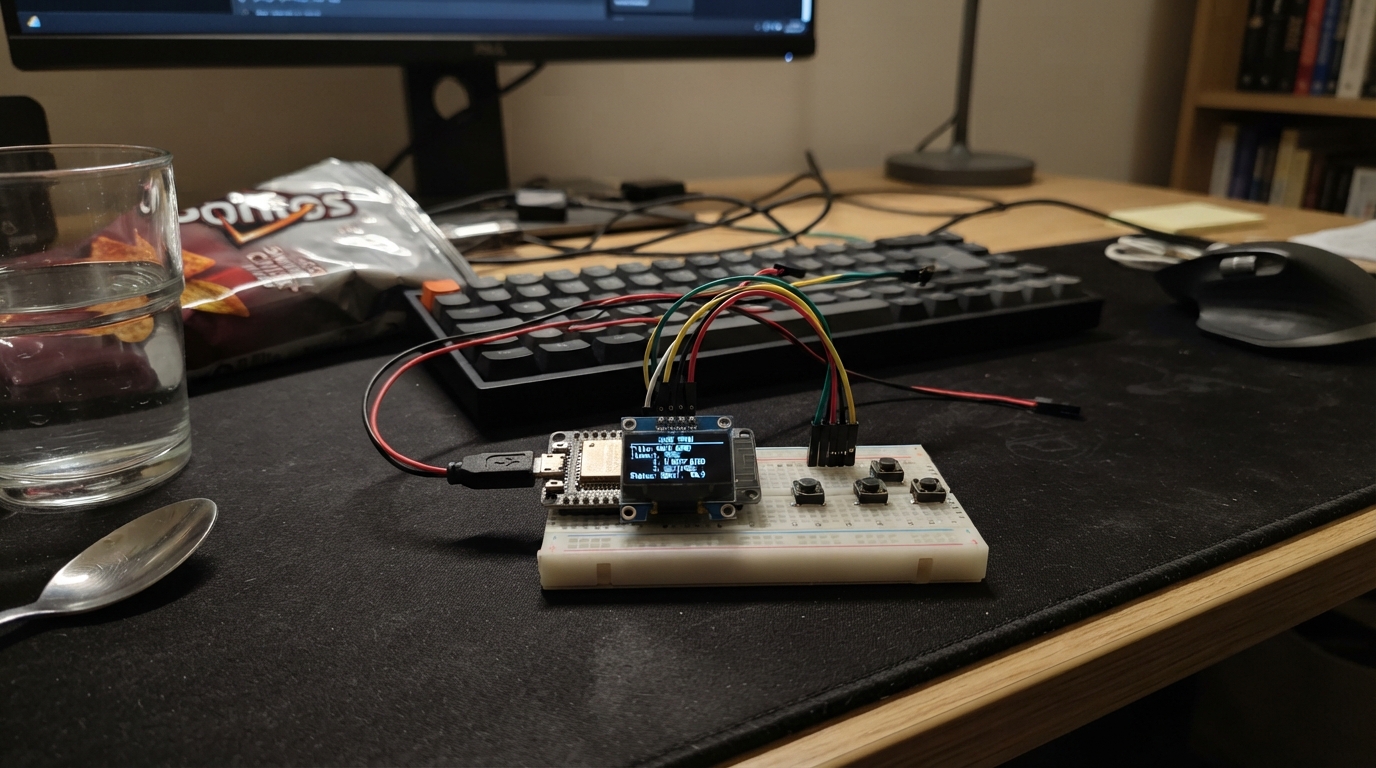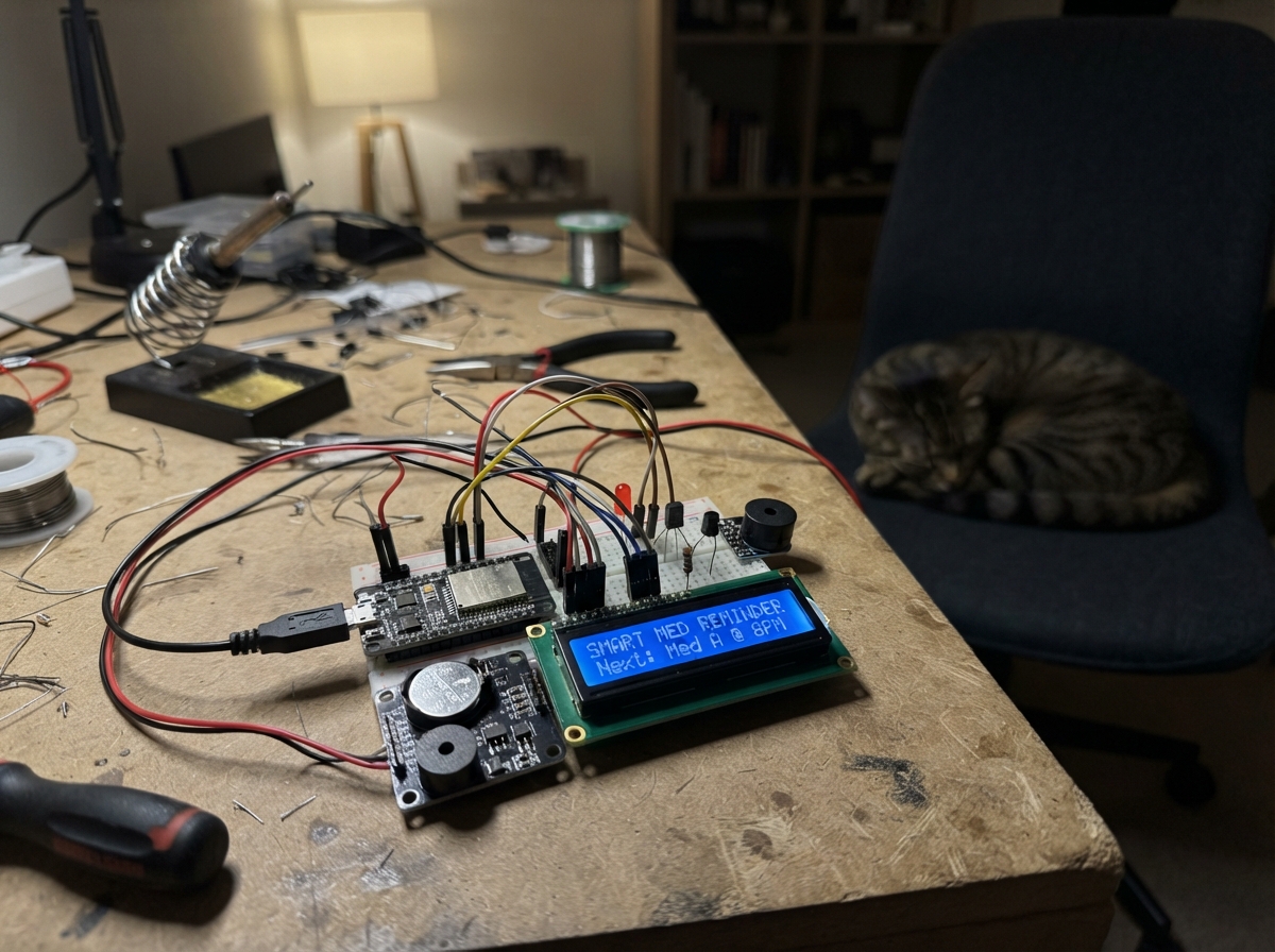
This smart medicine reminder uses an ESP32 microcontroller to alert users at four customizable times each day (morning, noon, evening, night) with a buzzer and LED. The system tracks whether doses are taken or missed, storing records in non-volatile memory for later review. A real-time clock module keeps accurate time even during power loss, while an I2C LCD display shows the current time and reminder status.
The guide provides a complete wiring diagram, parts list, and step-by-step assembly instructions for connecting the DS3231 real-time clock, LCD display, buzzer, LED indicator, push button, and reed switch (for detecting when the medicine cabinet is opened). Firmware is included with pre-configured reminder times that can be easily edited. The project runs on a rechargeable USB power bank, making it portable and practical for daily use.
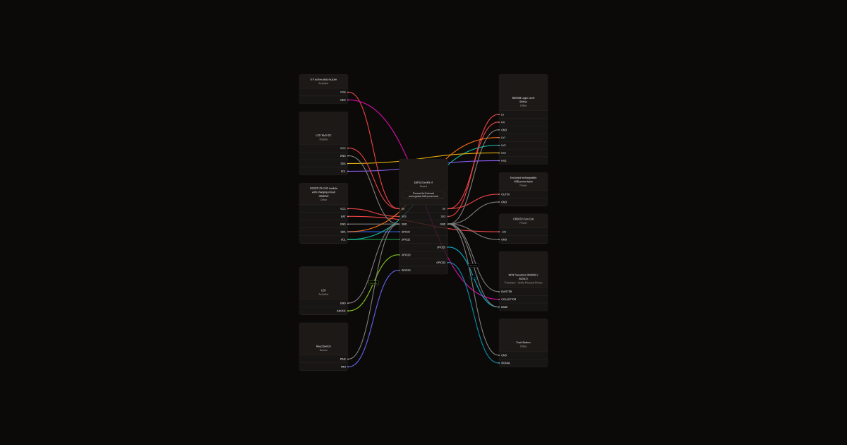
Wiring diagram
Gather all the parts
Assemble it in 5 steps
1. Buy ready-to-connect modules
Use pre-soldered headers, an enclosed genuine USB power bank, and a DS3231 ZS-042 whose charging resistor or diode has already been removed by the seller. Fit the CR2032 into its holder; BAT wiring represents the holder contact, not a loose wire.
- Never charge a CR2032. Do not use an exposed or damaged lithium cell.
2. Connect the shared data bus
RTC VCC goes to 3V3. SDA goes to GPIO21 (data) and SCL to GPIO22 (clock). Connect these to level-shifter LV1 and LV2. Its HV1 and HV2 go to LCD SDA and SCL. LV uses 3V3; HV and LCD use 5V. All grounds join.
- Never connect the 5 V LCD data lines directly to ESP32 pins.
3. Fit alert outputs
GPIO25 goes through 1 kohm to the transistor base. Add 100 kohm base to ground. Emitter goes to ground and collector to buzzer negative; buzzer positive goes to 5V. GPIO26 goes through 330 ohm to LED anode; LED cathode goes to ground. Verify the actual transistor package pinout with its seller before inserting it.
4. Fit button and lid sensor
Connect stop button between GPIO32 and ground. Connect reed switch between GPIO33 and ground. Mount its included magnet so the switch is closed with the lid closed and opens as the lid opens. Keep modules beside the half-size breadboard and use female jumpers rather than crowding it.
5. Power and test
Power the ESP32 through its USB socket using the power bank cable; the bank-to-5V wire in the diagram represents that USB connection, not a second supply. Disconnect the power bank before connecting the computer. Set INITIAL_TIME to Philippine local time and enable SET_CLOCK once, then disable it. Test a dose a few minutes ahead; press stop, then test lid opening and the 30-minute timeout separately. Read the last 64 history records over USB serial at 115200 baud.
- Recharge the power bank separately; simultaneous charging and operation are not assumed safe or supported. Alarms cannot sound while disconnected. The budget version stays awake and has no battery-level reading or low-battery LCD warning.
Review all connections
1. Connections between "bank" and "ESP32"
2. Connections between "rtc" and "ESP32"
3. Connections between "backup" and "ESP32"
4. Connections between "shift" and "ESP32"
5. Connections between "lcd" and "ESP32"
6. Connections between "buzzer" and "ESP32"
7. Connections between "q" and "ESP32"
8. Connections between "rb" and "ESP32"
9. Connections between "rpd" and "ESP32"
10. Connections between "rl" and "ESP32"
11. Connections between "indicator" and "ESP32"
12. Connections between "stop" and "ESP32"
13. Connections between "lid" and "ESP32"
Deploy the firmware
#include <Arduino.h>
#include <Wire.h>
#include <RTClib.h>
#include <LiquidCrystal_I2C.h>
#include <Preferences.h>
RTC_DS3231 rtc;
LiquidCrystal_I2C *lcd;
Preferences prefs;
constexpr int BUZZ=25, LEDPIN=26, BUTTON=32, REED=33;
// Philippine local time. Edit times here; keep them at least 30 minutes apart.
const uint8_t hours[4]={8,12,18,22}, minutes[4]={0,0,0,0};
const char *names[4]={"Morning","Noon","Evening","Night"};
// Set true for ONE deployment to set RTC, then false and deploy again.
constexpr bool SET_CLOCK=false;
const DateTime INITIAL_TIME(2026,11,16,8,0,0);
struct Record {uint32_t scheduled,event; uint8_t dose,taken;};
uint32_t done[4]={}, start=0;
int active=-1;
String lastStatus="No history";
bool ready=false, rawButton=false, stableButton=false, rawLid=false, stableLid=false;
uint32_t buttonChanged=0,lidChanged=0,lastPoll=0;
String oldRows[2];
void row(int r,String s){s=s.substring(0,16);while(s.length()<16)s+=' ';if(oldRows[r]!=s){lcd->setCursor(0,r);lcd->print(s);oldRows[r]=s;}}
void outputs(bool on){digitalWrite(BUZZ,on);digitalWrite(LEDPIN,on);}
void finish(bool taken,uint32_t now){
 outputs(false);
 Record rec={start,now,(uint8_t)active,(uint8_t)taken};
 uint32_t n=prefs.getUInt("count",0); char key[12];snprintf(key,sizeof(key),"h%02u",n%64);
 prefs.putBytes(key,&rec,sizeof(rec));prefs.putUInt("count",n+1);
 lastStatus=String(names[active])+ (taken?" TAKEN":" MISSED"); prefs.putString("last",lastStatus);
 String k="done"+String(active);done[active]=start;prefs.putUInt(k.c_str(),start);
 prefs.putInt("active",-1);active=-1;
 Serial.printf("%s at %lu\n",lastStatus.c_str(),(unsigned long)now);
}
bool edge(int pin,bool &raw,bool &stable,uint32_t &changed,bool activeHigh){
 bool v=digitalRead(pin)==(activeHigh?HIGH:LOW);if(v!=raw){raw=v;changed=millis();}
 if(millis()-changed>=40 && stable!=raw){stable=raw;return stable;}return false;
}
void setup(){
 Serial.begin(115200);pinMode(BUZZ,OUTPUT);pinMode(LEDPIN,OUTPUT);outputs(false);
 pinMode(BUTTON,INPUT_PULLUP);pinMode(REED,INPUT_PULLUP);Wire.begin(21,22);
 uint8_t address=0;for(uint8_t a: {uint8_t(0x27),uint8_t(0x3f)}){Wire.beginTransmission(a);if(Wire.endTransmission()==0){address=a;break;}}
 lcd=new LiquidCrystal_I2C(address?address:0x27,16,2);lcd->init();lcd->backlight();
 if(!address){Serial.println("LCD not found at 0x27/0x3F");return;}
 if(!rtc.begin()){row(0,"RTC not found");return;}
 if(SET_CLOCK)rtc.adjust(INITIAL_TIME);
 if(rtc.lostPower()){row(0,"Set RTC in code");row(1,"Alerts disabled");return;}
 prefs.begin("medicine",false);for(int i=0;i<4;i++){String k="done"+String(i);done[i]=prefs.getUInt(k.c_str(),0);}
 lastStatus=prefs.getString("last","No history");active=prefs.getInt("active",-1);start=prefs.getUInt("start",0);if(active<0||active>3)active=-1;
 rawButton=stableButton=digitalRead(BUTTON)==LOW;rawLid=stableLid=digitalRead(REED)==HIGH;
 ready=true;Serial.println("History: scheduled,event,dose,taken (1=taken,0=missed)");
 uint32_t n=prefs.getUInt("count",0);for(uint32_t j=n>64?n-64:0;j<n;j++){char k[12];snprintf(k,sizeof(k),"h%02u",j%64);Record r;if(prefs.getBytes(k,&r,sizeof(r))==sizeof(r))Serial.printf("%lu,%lu,%u,%u\n",(unsigned long)r.scheduled,(unsigned long)r.event,r.dose,r.taken);}
}
void loop(){
 if(!ready){delay(100);return;}
 bool pressed=edge(BUTTON,rawButton,stableButton,buttonChanged,false);
 bool opened=edge(REED,rawLid,stableLid,lidChanged,true);
 DateTime now=rtc.now();uint32_t t=now.unixtime();
 if(active>=0){if(t>=start && t-start>=1800)finish(false,t);else if(pressed||opened)finish(true,t);}
 if(active<0){for(int i=0;i<4;i++){
 DateTime d(now.year(),now.month(),now.day(),hours[i],minutes[i],0);uint32_t due=d.unixtime();
 if(t>=due && t-due<1800 && done[i]!=due){active=i;start=due;prefs.putUInt("start",start);prefs.putInt("active",i);break;}
 }}
 outputs(active>=0);
 if(millis()-lastPoll>=250){lastPoll=millis();char text[24];
 if(active>=0){snprintf(text,sizeof(text),"%s %02u:%02u",names[active],hours[active],minutes[active]);row(0,text);row(1,"Dose due: OPEN/OK");}
 else {snprintf(text,sizeof(text),"Time %02u:%02u:%02u",now.hour(),now.minute(),now.second());row(0,text);
 if((millis()/4000)%2)row(1,lastStatus);else{uint32_t next=UINT32_MAX;int ni=0;for(int i=0;i<4;i++){uint32_t d=DateTime(now.year(),now.month(),now.day(),hours[i],minutes[i]).unixtime();if(d<=t)d+=86400;if(d<next){next=d;ni=i;}}snprintf(text,sizeof(text),"Next %02u:%02u %s",hours[ni],minutes[ni],names[ni]);row(1,text);}}
 }
 delay(20);
}
Remix this project
Make it yours in one click
Open a full copy of this project in your own Schematik workspace, diagram, code, parts, and assembly steps included. Swap the sensor, add features, or redesign the whole thing with AI. The author's original stays untouched.