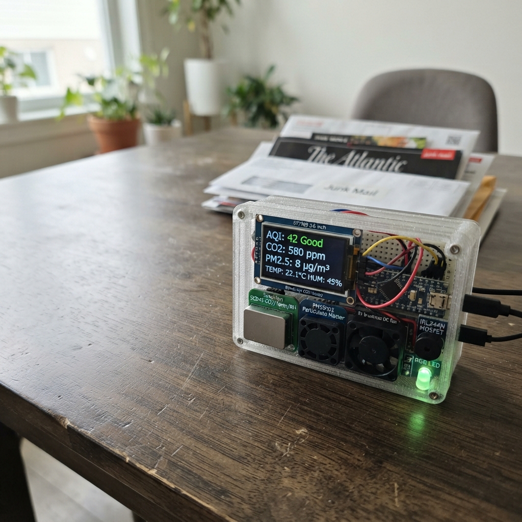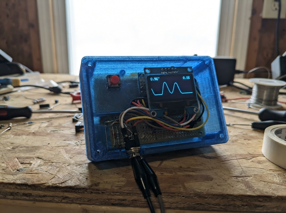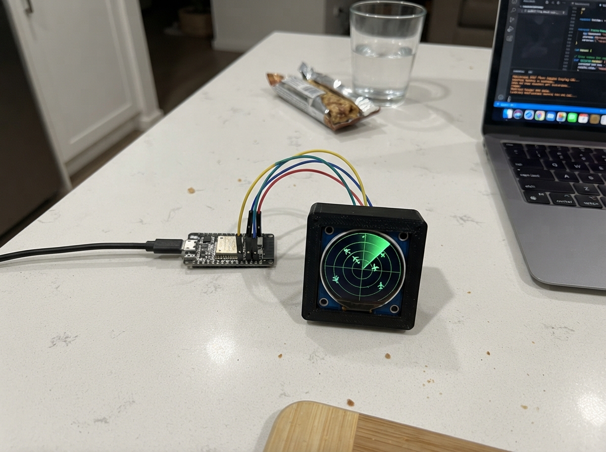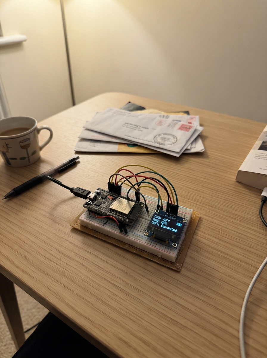
This project turns an ESP32 and small OLED screen into a real-time system monitor for a Windows PC. CPU, GPU, and RAM usage percentages display on the screen along with total memory consumption, all updated live over a serial connection.
The guide includes a wiring diagram for connecting the SSD1306 display to the ESP32, a complete parts list, the Arduino firmware for the microcontroller, and step-by-step assembly instructions. A companion Windows helper application sends system metrics to the ESP32 via USB serial, making this a practical desktop monitoring tool for any maker's workspace.
Wiring diagram
Gather all the parts
Assemble it in 2 steps
1. Connect the screen with USB unplugged
Use a 0.96-inch 128x64 SSD1306 I2C OLED and four jumper wires. Connect VCC to 3V3 (power), GND to GND (ground), SDA to GPIO21 (data), and SCL to GPIO22 (clock).
- Check the printed pin names, not their position. Reversed power can damage the display. Use 3V3, not 5V, to keep the data signals safe for the ESP32.
2. Power from the computer
Connect the ESP32 to your Windows PC with a USB data cable. Leave the screen powered only by the ESP32.
Review all connections
1. Connections between "oled" and "ESP32"
Deploy the firmware
#include <Arduino.h>
#include <Wire.h>
#include <Adafruit_GFX.h>
#include <Adafruit_SSD1306.h>
Adafruit_SSD1306 screen(128,64,&Wire,-1);
char line[96]; size_t pos=0; bool overflow=false;
int cpu=-1,ram=-1,gpu=-1,used=-1,total=-1;
bool online=false; uint32_t last=0;
void render(){
 screen.clearDisplay(); screen.setTextSize(1); screen.setTextColor(SSD1306_WHITE);
 screen.setCursor(0,0); screen.print("WINDOWS PC / USB");
 if(!online){screen.setCursor(0,24);screen.print("Waiting for PC...");screen.setCursor(0,44);screen.print("Run Windows helper");}
 else {
 const char* names[]={"CPU","RAM","GPU"}; int vals[]={cpu,ram,gpu};
 for(int i=0;i<3;i++){screen.setCursor(0,16+i*12);screen.print(names[i]);screen.print("  ");if(vals[i]<0)screen.print("N/A");else{screen.print(vals[i]);screen.print("%");}}
 screen.setCursor(0,56);screen.print(used/1024.0,1);screen.print(" / ");screen.print(total/1024.0,1);screen.print(" GB RAM");
 } screen.display();
}
void setup(){Serial.begin(115200);Wire.begin(21,22);if(!screen.begin(SSD1306_SWITCHCAPVCC,0x3C,true,false)){while(true)delay(1000);}render();}
void loop(){
 while(Serial.available()){
 char c=Serial.read();if(c=='\r')continue;
 if(c=='\n'){
 line[pos]=0; int a,b,cg,d,e;char extra;
 if(!overflow && sscanf(line,"PC,%d,%d,%d,%d,%d%c",&a,&b,&cg,&d,&e,&extra)==5 && a>=-1 && a<=100 && b>=0 && b<=100 && cg>=-1 && cg<=100 && d>=0 && e>0 && d<=e){
 bool changed=!online||a!=cpu||b!=ram||cg!=gpu||d!=used||e!=total;
 cpu=a;ram=b;gpu=cg;used=d;total=e;last=millis();online=true;if(changed)render();
 }pos=0;overflow=false;
 }else if(pos<sizeof(line)-1)line[pos++]=c;else overflow=true;
 }
 if(online && millis()-last>10000){online=false;render();}delay(5);
}
Remix this project
Make it yours in one click
Open a full copy of this project in your own Schematik workspace, diagram, code, parts, and assembly steps included. Swap the sensor, add features, or redesign the whole thing with AI. The author's original stays untouched.